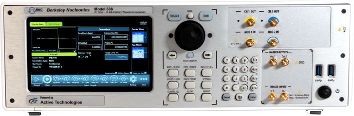
A 14-bit arbitrary waveform generator with sample rates programmable from 1 S/s to 20 GS/s, up to 9 Gpts of waveform memory, and two or four analog channels with up to 32 optional digital channels in one instrument. Three operating modes (AFG, True Arb, and optional Pulse Pattern Generator) cover function generation, arbitrary waveforms, and serial pattern testing.
Model 686 · Datasheet V1, 2024-04 · Specifications typical, verify against published datasheet
1Introduction
The Model 686 is a 14-bit arbitrary waveform generator. Sample rate can be programmed from 1 S/s up to 20 GS/s, with 14-bit vertical resolution, to ensure exceptional signal integrity. Arbitrary waveform memory reaches up to 9 Gpts.
Mixed signal generation is built in: 2 or 4 analog channels with up to 32 synchronized digital channels for debugging and validating digital design. The instrument offers three operation modes, Simple Rider AFG (DDS AFG mode), True Arb (variable clock arbitrary AWG mode), and PPG (pulse/serial pattern generator, optional). Digital outputs provide up to 10 Gb/s data rate in programmable CML standard, and a CML to LVTTL adapter is available.
An advanced sequencer with up to 16,384 user-defined waveforms makes it possible to generate complex signal scenarios with the most efficient memory usage. The Windows-based platform uses a 7 inch touchscreen with front panel buttons and a knob. The compact form factor is convenient for benchtop use and fully fits the 3U, 19 inch rackmount standard. LAN, USB-TMC, and GPIB interfaces are provided for remote control.
Features & Benefits
Sample rate programmable from 1 S/s up to 20 GS/s, with 14-bit vertical resolution, ensures exceptional signal integrity
Arbitrary waveform memory up to 9 Gpts
Mixed signal generation, 2 or 4 analog channels with up to 32 synchronized digital channels for debugging and validating digital design
Digital outputs provide up to 10 Gb/s data rate in programmable CML standard; CML to LVTTL adapter is available
Advanced sequencer with up to 16,384 user-defined waveforms for complex signal scenarios with efficient memory usage
Windows-based platform with 7 inch touchscreen, front panel buttons, and knob
Compact form factor, convenient for benchtop and fully fitting the 3U, 19 inch rackmount standard
LAN, USB-TMC, and GPIB interfaces for remote control
Applications
Optics, Photonics, RF Wireless
Quantum Applications
Automotive
Advanced Research Applications
Semiconductors Tests
Aerospace and Defense
2User Interface & Operating Modes
Simple Rider AFG: Function Generator Mode
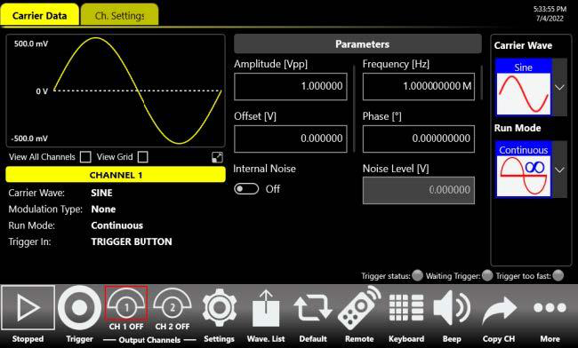
Simple Rider AFG function generator mode interface.
The Simple Rider AFG UI is designed for touch and has been developed to put all the capabilities of modern waveform generators right at your fingertips. All instrument controls and parameters are accessed through an intuitive UI that recalls the simplicity of tablets and modern smart phones. Touch features and gestures are available to engineers and scientists to create advanced waveforms or digital patterns in a few touches. The swipe gesture gives easy access to the output waveform parameters, a touch-friendly virtual numeric keypad improves the experience when entering data, and time-saving shortcuts with intuitive icons simplify instrument setup.
Simple Rider TrueArb: AWG Mode
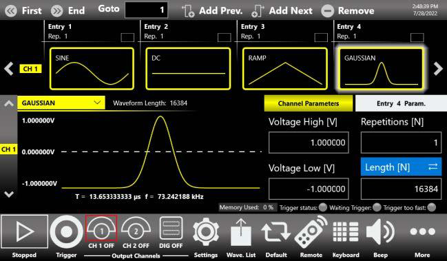
Simple Rider TrueArb AWG mode sequence editor.
In the Simple Rider True-Arb interface, users can define complex waveforms with up to 16,384 sequence entries of analog waveforms and digital patterns, and define their execution flow by means of loops, jumps, and conditional branches. Digital output combined and synchronized with analog output signals is an ideal tool to troubleshoot and validate digital design.
The waveform memory length of up to 9 GSamples on each channel, combined with up to 16,384 sequence entries and up to 4,294,967,294 repetitions, makes the Model 686 an ideal generator for the most demanding technical applications. Up to 4 instruments can be synchronized together to obtain a 16 analog, 128 digital channel generator. A dedicated synchronization bus guarantees intra-chassis synchronization. Arb Rider supports the standard Ethernet interface for remote control and easy customized instrument programming.
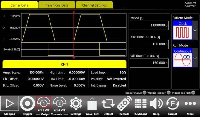
Simple Rider PPG: Pulse Pattern Generator Mode
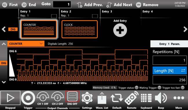
Simple Rider PPG pattern editor with predefined patterns.
The touch screen display interface allows creating pattern scenarios in a few screen touches. The Pulse Pattern Generator provides the capability to generate PRBS patterns and up to 12 MSymbols custom patterns where bit transitions can have arbitrarily user-defined shapes. The Model 686 Pulse Pattern Generator can generate patterns up to 6.5 Gbaud. The software architecture makes it possible to generate the patterns in different generation modalities and also to modulate the patterns with internal or external signals, with the purpose of generating different effects of noise (jitter, ripple, and similar).
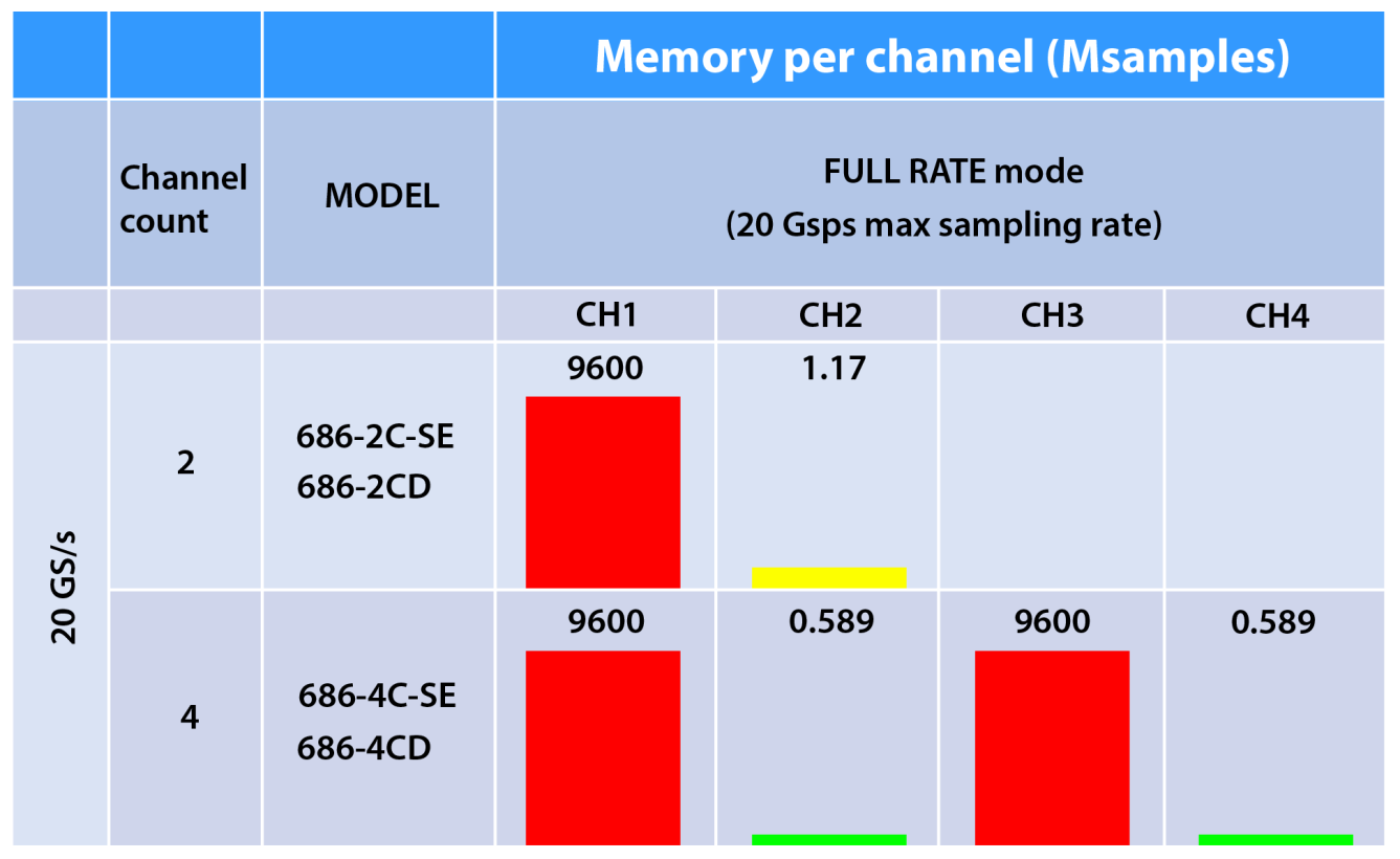
Memory per channel (Msamples), Full Rate mode at 20 GS/s.
Memory per channel (Msamples), Full Rate mode, 20 GS/s max sampling rate.
Channel count
Model
CH1
CH2
CH3
CH4
2
686-2C-SE / 686-2CD
9600
1.17
4
686-4C-SE / 686-4CD
9600
0.589
9600
0.589
4Options and Accessories
Item
Description
686-PAT
Serial Pattern Generator (SPG)
686-8DIG
8 CH digital license (available only for 4-channel models)
686-16DIG
16 CH digital license (available only for 4-channel models)
686-32DIG
32 CH digital license (available only for 4-channel models)
686-FSS
Fast Sequence Switch
686-WAR
3 years warranty extension
RIDER-MINI-SAS-HD
Mini SAS HD cable for digital probe, 8 differential signals (available only for 4-channel models)
RIDER-686-SYNC
Synchronization cable for all 686 models
AT-DTTL8
LVDS to LVTTL digital adapter probe (available only for 4-channel models)
AT-LVDS-SMA8
CML to SMA digital adapter cable (available only for 4-channel models)
GP-IB / USB-TMC
GPIB and USB-TMC ports for remote control
RIDER-RACK
Rackmount kit for Rider instrument system
5General Specifications
All specifications are typical unless noted otherwise. The guaranteed performances are referred to a calibrated instrument that has been stored for a minimum of 2 hours within the operating temperature range of 5 °C to 40 °C and after a 45-minute warm-up period, within ±10 °C after auto-calibration.
Parameter
686-2C-SE / 686-4C-SE
686-2CD / 686-4CD
Operating Mode
AFG Mode, True Arb Mode, SPG Mode (optional)
Analog channels
2 (2C models), 4 (4C models)
Markers
2 (2C models), 4 (4C models)
Digital Channels
– (2C models), 32 (4C models)
Output Type
Single ended DC coupled
Differential DC coupled
Output Impedance
Single ended: 50 Ω
Single ended: 50 Ω Differential: 100 Ω
Connectors
SMA on front panel
DC Amplitude range
±2.5 V (into 50 Ω)
±0.625 V Se. (into 50 Ω) ±1.25 V Diff. (into 100 Ω)
Amplitude resolution
500 µV (nom), 5 digits
100 µV (nom), 5 digits
Amplitude accuracy
±(1.5% of |setting| + 15 mV)3
±(1% of |setting| + 2 mV)3
DC baseline hardware offset resolution
< 4 mV or 4 digits
Offset range (50 Ω into 50 Ω)
-2.5 V to +2.5 V
-2 V to +2 V
Offset range (50 Ω into High Z load)
-2.5 V to +2.5 V
-4 V to +4 V
Offset accuracy (50 Ω into 50 Ω) (guaranteed)
±(1% of |setting| + 15 mV)
±(1% of |setting| + 5 mV)
AC accuracy (1 kHz sine, 0 V offset, > 5 mVp-p, 50 Ω load) (guaranteed)
±(1% of setting [Vpp] + 5 mV)3
3 The specification is guaranteed in the range 0% to 80% of full scale output.
6True Arb – Baseband Mode Specifications
Parameter
686-2C-SE / 686-4C-SE
686-2CD / 686-4CD
Operating Modes
Full Rate Mode (variable clock), Half Rate Mode (variable clock)
Max waveform memory, Full Rate (20 GS/s), 686-2C-SE / 686-2CD
CH1: 9.6 Gsamples; CH2: 1.17 Msamples
Max waveform memory, Full Rate (20 GS/s), 686-4C-SE / 686-4CD
CH1, CH3: 9.6 Gsamples; CH2, CH4: 589 ksamples
Waveform Granularity
1 if the entry length is > 8928 samples; 288 if entry length is ≥ 288 and ≤ 8928 samples
Sequence Length
1 to 16384
Sequence Repeat Counter
1 to 4294967294 or infinite
Timer range
17.6 ns to 429 ms
Timer resolution
±1 sampling clock cycle
Analog channel to channel skew, range
0 to 1.63 µs
Skew resolution
4C models: CHx to CHx (x=1,2,3,4): 1 sampling clock cycle; CH1/CH2 couple to CH3/CH4 couple: 100 fs. 2CH models: CHx to CHx (x=1,2): 100 fs
Skew accuracy
±(1% of setting + 20 ps)
Initial skew
< 20 ps
Calculated bandwidth (0.35 / rise or fall time10-90)
≥ 5 GHz
≥ 5.8 GHz
Measured 3 dB bandwidth (sin(x)/x compensated)
5.8 GHz
SFDR @ 100 MHz5 (DC to Fs/2, Fs = 20 GSa/s)
< -65 dBc
SFDR (DC to Fs/2, Fs = 20 GSa/s, 18 mHz to ≤ 100 MHz)
< -65 dBc
Rise/fall time (1 Vp-p single-ended 20% to 80%)
≤ 50 ps
≤ 45 ps
Rise/fall time (1 Vp-p single-ended 10% to 90%)
≤ 70 ps
≤ 60 ps
Overshoot (1 Vp-p single-ended)
< 8%
< 6%
Random jitter on clock pattern
< 2 ps
4 When using the External Clock Input the Sample Rate must be in the range 0 to 20 GHz, but the entire Sample Rate interval is not continuous (see the corresponding section in the User Manual). 5 Measured excluding Fs – 2·fout and Fs – 3·fout and excluding harmonics.
7AFG Mode Specifications
Parameter
686-2C-SE / 686-4C-SE
686-2CD / 686-4CD
Amplitude range
0 to 5 Vpp (into 50 Ω)
0 to 2.5 Vpp Diff. (into 100 Ω) 0 to 1.25 Vpp Se. (into 50 Ω)
6 For single-ended models, the spurious are evaluated @ 1 Vpp single-ended nominal output amplitude.
Square Waves
Parameter
Specification
Channels with Square Wave
All Channels
Frequency Range
18 mHz to ≤ 2.5 GHz
Rise/fall time (10% to 90%)
120 ps
Rise/fall time (20% to 80%)
90 ps
Overshoot (1 Vp-p)
< 2%
Jitter (rms)
< 2 ps
Pulse Waves
Parameter
Specification
Channel with Pulse Wave
All Channels
Frequency Range
18 mHz to ≤ 2.5 GHz
Pulse Width
150 ps to (Period – 150 ps)7
Pulse width resolution
20 ps or 15 digits
Pulse duty
0.1% to 99.9% (limitations of pulse width apply)
Leading/trailing edge transition time (10% to 90%)
120 ps to 1000 s
Transition time resolution
2 ps or 15 digits
Overshoot (1 Vp-p)
< 2%
Jitter (rms, with rise and fall time ≥ 400 ps)
< 2 ps
7 Below 150 ps width, the pulse amplitude will have some reduction with respect to the set value.
Double Pulse Waves
Parameter
Specification
Frequency Range (Vpp = |Vpp1| + |Vpp2|)
18 mHz to ≤ 1.25 GHz: 10 Vpp; 18 mHz to ≤ 1.25 GHz: 5 Vpp Diff. (18 mHz to ≤ 1.25 GHz: 2.5 Vpp Se.)
Other Pulse Parameters
Same as Pulse Waves
Ramp Waves
Parameter
Specification
Frequency Range
18 mHz to 250 MHz
Linearity (< 10 kHz, 1 Vp-p, 100%)
≤ 0.1%
Symmetry
0% to 100%
Other Waves
Parameter
Frequency Range
Exponential Rise, Exponential Decay
18 mHz to 250 MHz
Sin(x)/x, Gaussian, Lorentz, Haversine
18 mHz to 500 MHz
Additive Noise
Parameter
Specification
Bandwidth (-3 dB)
4 GHz
Level
0 V to 2.5 V - abs(carrier max value [Vpk]); 0 V to 0.625 V single-ended - abs(carrier max value [Vpk]); 0 V to 1.25 V differential - abs(carrier max value [Vpk])
Resolution
1 mV
Arbitrary
Parameter
Specification
Number of Samples
2 to 16384
Frequency Range
1 µHz to 2.5 GHz
Analog Bandwidth (-3 dB)
2.9 GHz
Rise/fall time (10% to 90%)
120 ps
Rise/fall time (20% to 80%)
90 ps
Jitter (rms)
< 2 ps
Frequency
Parameter
Specification
Frequency Resolution (Sine, square, pulse, arbitrary, Sin(x)/x)
18 mHz or 15 digits
Frequency Resolution (Gaussian, Lorentz, Exponential Rise, Exponential Decay, Haversine)
18 mHz or 14 digits
Frequency Accuracy, Non-ARB
±2.0 ppm of setting | ±500 ppb of setting (Opt.)
Frequency Accuracy, ARB
±2.0 ppm of setting ±1 µHz | ±500 ppb of setting ±1 µHz (Opt.)
Modulations
Parameter
Specification
Amplitude Modulation (AM), carrier waveforms
Standard waveforms (except Pulse, DC and Noise), ARB
AM modulation source
Internal or external
AM internal modulating waveforms
Sine, Square, Ramp, Noise, ARB
AM modulating frequency
Internal: 18 mHz to 80 MHz; External: 1 GHz max.
AM depth
0.00% to 120.00%
Frequency Modulation (FM), carrier waveforms
Standard waveforms (except Pulse, Square, DC and Noise), ARB
FM modulation sources
Internal or external
FM internal modulating waveforms
Sine, Square, Ramp, Noise, ARB
FM modulating frequency
Internal: 18 mHz to 80 MHz; External: 1 GHz max.
FM peak deviation
DC to 6.5 GHz
Phase Modulation (PM), carrier waveforms
Standard waveforms (except Pulse, Square, DC and Noise), ARB
PM modulation source
Internal or external
PM internal modulating waveforms
Sine, square, ramp, noise, ARB
PM modulating frequency
Internal: 18 mHz to 80 MHz; External: 1 GHz max.
PM phase deviation range
0° to 360°
Frequency Shift Keying (FSK), carrier waveforms
Standard waveforms (except Pulse, Square, DC and Noise), ARB
FSK modulation source
Internal or external
FSK internal modulating waveforms
Square
FSK key rate
Internal: 18 mHz to 80 MHz; External: 1 GHz max.
FSK hop frequency
1 µHz to 6.5 GHz
FSK number of keys
2
Phase Shift Keying (PSK), carrier waveforms
Standard waveforms (except Pulse, Square, DC and Noise), ARB
PSK modulation source
Internal and external
PSK internal modulating waveform
Square
PSK key rate
Internal: 18 mHz to 80 MHz; External: 1 GHz max.
PSK hop phase
0° to +360°
PSK number of keys
2
Pulse Width Modulation (PWM), carrier waveforms
Pulse
PWM modulation source
Internal or external
PWM internal modulating waveforms
Sine, Square, Ramp, Noise, ARB
PWM modulating frequency
Internal: 18 mHz to 80 MHz; External: 1 GHz max.
PWM deviation range
0% to 50% of pulse period
Sweep
Parameter
Specification
Type
Linear, Logarithmic, staircase, and user defined
Waveforms
Standard waveforms (except Pulse, DC and Noise), ARB
Sweep time
4 ns ≤ Rise time + Hold time + Fall time ≤ 2000 s
Rise/Hold/return times
0 to 2000 s
Rise/Hold/return time resolution
1 ps or 12 digits
Total sweep time accuracy
≤ 0.4%
Start/stop frequency range
18 mHz to Max Waveform frequency (see Frequency Range for the specific waveform)
150 ps to Symbol duration for Custom, PRBS and Go-Through pattern; 150 ps to Period/2 for Clock Pattern; 150 ps to (Period – 150 ps) for Pulse Pattern
Clock Pattern
Parameter
Specification
Max clock pattern frequency
3.25 GHz
Pattern levels
2 levels
Overshoot (1 Vp-p)
< 2%
Jitter (rms)
< 2 ps
Custom Pattern
Parameter
Specification
Max custom pattern rate
Up to 6.5 Gbaud
Pattern levels
2, 3 or 4 levels
Predefined custom patterns
Zero, one, clock, counter
Pattern memory channel
Up to 12 MBit (2 levels), up to 6 MSymbols (3 or 4 levels) for 2-channel models; up to 6 MBit (2 levels), up to 3 MSymbols (3 or 4 levels) for 4-channel models
AFG: 75 MTps on Rising/Falling Edge, 100 MTps on Both Edges; True Arb mode: 1 / (Period of the Analog Waveform + 293 DAC Clock period). MTps = Mega Transitions per second
Reference Clock Input
Parameter
Specification
Connector type
SMA on rear panel
Input Impedance
50 Ω, AC coupled
Input voltage range
0.2 Vpp to 3.3 Vpp
Damage level
Maximum input voltage: 3.6 Vpp; Maximum input power: 15 dBm (50 Ω)
Frequency range
5 MHz to 500 MHz
Frequency resolution
1 Hz
Reference Clock Output
Parameter
Specification
Connector type
SMA on rear panel
Output impedance
50 Ω, AC coupled
Frequency
10 MHz TCXO | 100 MHz VCOCXO (Optional)
Initial accuracy @ 25 °C
± 1.0 ppm | ± 500 ppb (Opt.)
Aging
± 1.0 ppm/year | ± 500 ppb/year (Opt.)
Stability vs. temperature
± 1 ppm | ± 50 ppb (Opt.)
Amplitude
1.65 Vpp
Phase Noise @ 10 MHz carrier
-120 dBc/Hz at 100 Hz; -140 dBc/Hz at 1 kHz; -150 dBc/Hz at 10 kHz
External Clock Input
Parameter
Specification
Connector type
SMA on rear panel
Input impedance
50 Ω, AC coupled
Frequency8
True Arb: SampleRate / N where N = 8, 16, 32, 64 for every SampleRate. AFG: 312.5 MHz, 625 MHz, 1250 MHz or 2500 MHz (selectable)
Input power range
+0 dBm to +10 dBm
Damage level
15 dBm
Sync Clk Out
Parameter
Specification
Connector type
SMA on rear panel
Output impedance
50 Ω, AC coupled
Frequency
AFG Mode: 20 GHz / N where N = 40, 80, 160, ..., 5120; AWG Mode: Sampling Rate / N, N = 64, 128, ..., 8192
8 When using the External Clock Input the SampleRate must be in the range 0 to 20 GHz, but the entire Sample Rate interval is not continuous (see the corresponding section in the User Manual).
12Power, Environmental & System Specifications
Power
Parameter
Specification
Source voltage and frequency
100 to 240 VAC ± 10% @ 45-66 Hz
Max. power consumption
Max. 250 W
Environmental Characteristics
Parameter
Specification
Temperature (operating)
+5 °C to +40 °C (+41 °F to 104 °F)
Temperature (non-operating)
-20 °C to +60 °C (-4 °F to 140 °F)
Humidity (operating)
5% to 80% relative humidity with a maximum wet bulb temperature of 29 °C at or below +40 °C (upper limit de-rates to 20.6% relative humidity at +40 °C). Non-condensing.
Humidity (non-operating)
5% to 95% relative humidity with a maximum wet bulb temperature of 40 °C at or below +60 °C (upper limit de-rates to 29.8% relative humidity at +60 °C). Non-condensing.
Altitude (operating)
3,000 meters (9,842 feet) maximum at or below 25 °C
Altitude (non-operating)
12,000 meters (39,370 feet) maximum
EMC and Safety
Parameter
Specification
Safety
EN61010-1
Main Standards
EN 61326-1:2013, Electrical equipment for measurement, control and laboratory use, EMC requirements, Part 1: General requirements
Immunity
EN 61326-1:2013
System Specifications
Parameter
Specification
Display
7 inch, 1024x600, capacitive touch LCD
Operating System
Windows 10
External Dimensions
W 445 mm, H 135 mm, D 320 mm (3U 19 inch rackmount)
Weight
Max. 26.45 lbs (12 kg)
Front panel connectors
CH N OUTPUT (SMA), MOD N INPUT (SMA), MARKER N OUT (SMA), TRG IN N (SMA) where N=2,4 depending on the model; 2 USB 3.0 ports
Rear panel connectors
Ref. Clk. IN (SMA); Ref. Clk. Out (SMA); Sync Clk Out (SMA); Ext Clk IN (SMA); Sync IN (QSFP cable); Sync OUT (QSFP cable); Pattern Jump In (DSUB15) (AWG-7000-FSS opt. only); POD X[7..0] where X=A,B,C,D (Customized Mini SAS HD); External Monitor ports (one or more); 2 USB 2.0 ports or more; 4 USB 3.0 ports; Ethernet port (10/100/1000BaseT, RJ45); 2 PS/2 keyboard and mouse ports; 2 DPI ports; 1 DVI port
Hard Disk
1 TB SSD or better
Processor
Intel® Pentium Gold G6400 4 GHz (or better)
Processor Memory
32 GB or better
13Applications
Optics & Photonics, RF Wireless
The Model 686 is an ideal choice for the frontier of science and technology experiments and cutting-edge challenges like High Energy Physics, optical, laser and photonics, and RF Wireless communication. The Model 686 series instrument can create virtually any signal, analog or digital, ideal or distorted, standard or custom. You can build complex RF/IF/IQ waveforms, extremely small-width high-amplitude pulses to drive electro/acousto-optic modulators and pulsed laser diodes, or use it in quantum optics experiments such as manipulating nitrogen vacancy color centers in diamond.
Highlights: drive electro-optic modulator; modulating and driving laser diode; quantum optics emitters testing; RF Wireless digital modulation.
Quantum Applications
Emerging quantum technologies such as Quantum Sensing and Quantum Key Distribution will be fundamental tools for secure communication and for how we measure, navigate, study, explore, see, and interact with the world by sensing changes in motion and in electric and magnetic fields. The Model 686 generates pulses with ultra-fast rise and fall time, Gaussian shapes, multi-level PAM and PRBS signals, complex pulse trains, and pulsed RF signals with impairments that are key factors for these tests.
Highlights: PRBS signal generation; QKD and Quantum sensing; cold atoms; manipulate nitrogen vacancy color center in diamond; minimum delay between Trigger In and Analog Out; up to 16 analog channels and 128 digital channels fully synchronized; built-in sequencer with conditional/unconditional/dynamic jump features, two independent trigger inputs, up to 4 marker outputs.
Automotive
Next-generation advanced driver-assistance systems (ADAS) require camera and radar systems with increasingly high resolution. Camera, LIDAR, Radar, and Ultrasound devices need higher bandwidth and lower latency. The Model 686 combines 20 GS/s with 14-bit vertical resolution, an ideal instrument for generating the real-world signals necessary to emulate the most demanding testing cases.
Highlights: electrical standards emulation up to 5 V; physical layer testing; sensor testing; EMI debugging, troubleshooting, and testing.
Advanced Research Applications
The Model 686 offers an excellent balance between signal amplitude and bandwidth: you can generate 5 Vpp pulses with more than 6.5 GHz of analog bandwidth. The combination of ultra-fast edge and minimum pulse width generation, excellent dynamic range, and an easy-to-use interface suits scientists and engineers working on large experiments such as accelerators, tokamaks, or synchrotrons. Pulses can be generated for applications such as Pulse Electron Beam or X-Ray sources, Flash X-ray radiography, lighting pulse simulators, and high power microwave modulators.
Highlights: emulation of detectors; emulation of signal sources adding noise; generation/playback of real-world signals.
Semiconductors Test
Smaller footprints, higher data throughput, and lower power requirements enable technologies such as SATA, USB, and PCI Express. The Model 686 series allows testing of these high-speed devices, providing up to 16 analog output channels with a maximum data rate of 8 Gbps and PCI-Express Gen. 3 debugging. Fast edges and pulse generation can be used to characterize fast power devices.
Highlights: high-speed serial testing; semiconductor characterization; high-speed clock generation; frequency response, intermodulation distortion, and noise-figure measurements; pulse pattern generator.
Aerospace and Defense
Radar, Lidar, and Sonar design and testing match the Model 686 series. The capability to generate high-bandwidth signals can be used on digital modulation systems for radio applications or other I/Q signal modulation. High-speed signal generation combined with the advanced sequencer and its fast sequence switch feature enables emulation of complex real-world signal scenarios.