The Mission
A pulsed solid-state laser is a sequence of timed events. The flashlamp or pump diodes fire, the gain medium builds up energy, and then the Q-switch opens to dump that energy into a short, high-peak-power pulse. Adding a Pockels cell for pulse picking or cavity dumping adds another gate that has to open and close on a tight schedule. Get the delays right and the laser runs clean. Get them wrong and you lose energy, stability, or the pulse entirely.
A pulse and delay generator owns that schedule. It sets the lamp-to-Q-switch delay, gates the Pockels cell driver, and triggers diagnostics and cameras, all referenced to one start pulse.
The Challenge
Timing here spans a wide range. The lamp-to-Q-switch delay sits in the tens to hundreds of microseconds, while the Pockels cell gate that picks a single pulse from a train can be only a few nanoseconds wide and has to land in a fixed window every shot. Low jitter keeps pulse energy repeatable. A fast, clean edge matters because the Pockels cell driver and Q-switch electronics trigger on that edge, and overshoot or ringing can cause a false or early gate.
Many labs also need adjustable-amplitude outputs to drive a specific trigger threshold, optical outputs to cross ground potentials in a high-voltage cage, and the ability to insert or remove a channel without re-cabling.
Recommended Berkeley Nucleonics Solutions
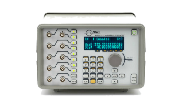
The Model 575 is built for exactly this work. It offers 2, 4, or 8 channels with 250 ps resolution and the deepest mix of output modules in the line, including TTL, adjustable high-voltage, and optical inputs and outputs, so you can gate a Pockels driver on one channel and fire a flashlamp on another while crossing potentials over fiber. The Model 577 covers the same ground in a full-featured 4 or 8 channel benchtop with rep rates to 20 MHz and channel-to-channel jitter below 50 ps RMS.
When the Pockels or pulse-picking gate has to be genuinely fast, the Model 765 delivers a 70 ps rise time (20 to 80 percent), 300 ps minimum width, 10 ps delay and width resolution, and around 4 ps RMS jitter, with adjustable amplitude up to 5 Vpp and an adjustable baseline offset. That edge speed drives a Pockels cell trigger with margin to spare. For a compact, lower-cost setup or a portable rig, the Model 525 packs six independent channels into a USB-powered, book-sized unit with 4 ns resolution.
Why It Works
These generators separate the slow and fast halves of the laser schedule onto independent channels referenced to one trigger, so the lamp-to-Q-switch delay and the nanosecond Pockels gate stay locked together shot after shot. Adjustable amplitude meets the trigger threshold of real driver electronics, optical I/O on the 575 keeps timing clean across high-voltage boundaries, and the 765 supplies the fast, low-overshoot edge a Pockels cell wants.
Getting Started
Berkeley Nucleonics application engineers help match channel count, edge speed, jitter budget, and output module to your timing diagram before you order. Send a block diagram or a short description of the events you need to synchronize, and we will return a configuration recommendation.
Email info@berkeleynucleonics.com or call 800-234-7858. Browse the full Pulse & Delay Generator documentation for datasheets, manuals, and ordering guides.