1Description
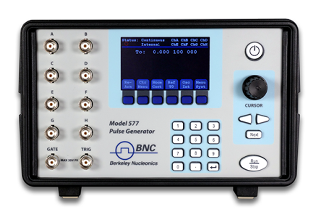
The Model 577 Digital Delay / Pulse Generator represents the latest in timing capabilities. With up to 8 outputs configurations as varied as the applications the product serves, the Model 577 is clearly our most versatile instrument.
The 250 ps width and delay resolution and 50 ps internal jitter give gating, triggering, delaying, clocking and synchronizing a precision sufficient for nearly every application. Add to this performance: optical or electrical outputs and inputs, pulse picking capabilities, selectable external clocks and USB/RS232 programming.
2Features & Applications
Features
- Outputs: 4 or 8 Independent Channel Outputs
- Pulse Width: 10 ns - 1000 s
- Pulse Delay: 0 ns - 1000 s
- Pulse and Delay Resolution: 250 ps
Applications
- ICCD/PIV Testing
- Laser Triggering / Gating
- Pulse DUTs and Pump Lasers
- Radar / Sonar Simulation
- High Speed Photography
3Capabilities & Options
Selectable Clock Reference
The Model 577 offers additional inputs and outputs for external clock syncing. Specify your input / output reference frequency (10 MHz to 100 MHz). Sync with the Mode Lock Oscillator of a laser, or phase lock multiple units with one clock.
Flexible Gating Options
The Model 577 is packed with gating options for almost any setup. You may gate with a channel or on any input. You may gate individual channels or gate all. Gate immediately (output inhibit) or gate after a pulse (pulse inhibit).
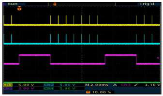
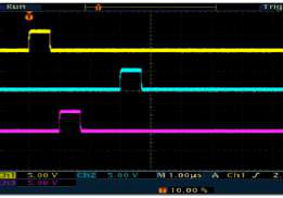
Individual Rates
Each channel may have patterns that may be continuous, a single burst, a series of repetitive bursts, a sub-harmonic of a previous channel, a single timed pulse. All the while the pulses have their own delay and widths. A typical application is to have a channel issue series of pulses to trigger flashlamps or laser diodes. Other channels can trigger Q-switches, detectors and cameras with single timed pulses synchronized to the pulse series in the first.
Auto-Save
Forgot to save your settings? The Model 577 stores your setup configurations while powering down. Recall is automatic on power-up.
Dual Input Panel Connectors
The Model 577 offers two inputs for triggering or gating. User may specify electrical or optical input signals, and configure any trigger / gate combination. Use Trigger #2 to disable a triggered pulse train.
Front Panel Optical
Many applications benefit from optical signals. For noisy environments, or communications applications, we offer an LED output stage at the front panel. This modular option can be configured for 2, 4, or 8 outputs at 820 nm or 1300 nm.
Front Panel High Voltage
Our modular architecture allows us to offer expanded functionality on user-selected front panel outputs. We offer a front panel High Voltage option (adjustable from 5 V to 45 V, 200 mV steps) on 2 or 4 channels.
Combined Output Types
The outputs are configured in modules and output types are combined in pairs. Thus one may select optical, standard electrical or high voltage electrical in pairs for their instrument. For example, an 8 channel unit may have optical, standard electrical and high voltage outputs all on one instrument. Custom or additional output modules may be added as the need arises.
Field Programmability
The instrument can now have functions upgraded in the field, such as a special or custom feature upgrade via a fully programmable FPGA.
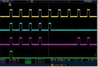
Pulse Picking
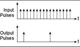
Using an external modulation up to 100 MHz, you may select 1 out of every X pulses for a given channel.
Custom Output Modes
Custom modules give users an expanded list of capabilities with the Model 577. One example is our TZ-50 option, which allows customers to output at a 4 V TTL signal into 50 ohms load.
Negative Delay
Use the handy negative delay feature to reference one channel with respect to another channel in positive or negative time increments. By allowing a channel to reference another channel as its trigger, you can synchronize the channels with respect to each other.
4Internal Rate Generator
| Rate (T0 period) | 0.001 Hz to 20.000 MHz (1000 s – 50 ns) |
| Resolution | 5 ns |
| Accuracy | 1 ns + (0.0001 x period) |
| T0 Period Jitter | < 50 ps RMS |
| Time Base | 100 MHz, low jitter PLL |
| Oscillator | 50 MHz, 50 ppm crystal oscillator |
| System Output Modes | Single, Normal, Burst, Duty Cycle, External Gate/Trigger |
| Burst Mode | 1 to 10,000,000 pulses |
| Duty Cycle Mode | 1 to 10,000,000 pulses ON and/or OFF |
| Pulse Control Modes | Internally triggered, externally triggered or external gate |
5Timing Generator
| Pulse Width Range | 10 ns - 1000 s |
| Width Accuracy | 1 ns + 0.0001 x width setting |
| Width Resolution | 250 ps |
| Pulse Delay Range | 0 - 1000 s |
| Delay Accuracy | 1 ns + 0.0001 x delay setting |
| Delay Resolution | 250 ps |
| Jitter (channel to channel) | < 50 ps RMS |
| Output Multiplexer | Any/all channels may be OR’d to any/all outputs. |
| Time Base | Same as the internal rate generator |
| Channel Output Modes | Single, Normal, Burst, Duty Cycle |
| Burst Mode | 1 to 10,000,000 pulses |
| Duty Cycle Mode | 1 to 10,000,000 pulses ON and/or OFF |
| Wait Counts | 1 to 10,000,000 pulses |
| Channel Control Modes | Internally triggered or external gated. Each channel may be independently set to either mode. |
6Standard Module Specification
TTL/Adjustable Dual Channel Output Module (Standard)
| TTL/CMOS Mode | |
|---|---|
| Output Impedance | 50 Ω |
| Output Level | 4.0 V (typical) into 1 kΩ |
| Rise Time | < 3 ns (1.5 ns typical) |
| Jitter (channel to channel) | < 50 ps RMS |
| Adjustable Mode | |
|---|---|
| Output Level | 2 V to 20 VDC into Hi-Z 1 V to 10 VDC into 50 Ω |
| Amplitude Resolution | 10 mV |
| Current | 200 mA typical, 400 mA (short pulses) |
| Rise Time | 15 ns (typical) @ 20 V into Hi-Z 25 ns typ @ 10 V into 50 Ω |
| Slew Rate | > 0.1 V/ns |
| Overshoot | < 1 V + 10% of pulse amplitude |
7Trigger / Gate Dual Input Module (Standard)
| Trigger Input | |
|---|---|
| Function | Generate individual pulses, start a burst or continuous stream |
| Rate | DC to 1 / (200 ns + longest active pulse). Maximum of 5 MHz |
| Slope | Rising or Falling |
| Threshold | 200 mV to 15 VDC |
| Maximum Input | 60 V Peak |
| Resolution | 10 mV |
| Trigger Accuracy | ±3% of Threshold Voltage |
| Impedance | 1.2K ohm |
| Trigger Jitter | < 800 ps RMS |
| Insertion Delay | < 110 ns |
| Minimum Pulse Width | 20 ns |
| Pulse Inhibit Delay | < 150 ns RMS |
| Output Inhibit Delay | < 100 ns RMS |
| Gate Input | |
|---|---|
| Mode | Pulse Inhibit or Output Inhibit |
| Polarity | Active High or Active Low |
8Output Module Options
Option TZ50 - TTL 50 Ω Output Impedance
| TTL/CMOS Mode | |
|---|---|
| Output Level | 4.0 V typ into 50 Ω |
| Rise Time | < 3 ns (2 ns typical) |
| Slew Rate | 0.5 V/ns |
| Jitter - Channel to Channel | < 50 ps RMS |
| Adjustable Mode | |
|---|---|
| Output Level | 2 V to 20 VDC into 1 kΩ or 1 V to 10 VDC into 50 Ω |
| Amplitude Resolution | 10 mV |
| Current | 200 mA typical, 400 mA (short pulses) |
| Rise Time (10% - 90%) | 15 ns (typical) @ 20 V into Hi-Z (25 ns typ @ 10 V into 50 Ω) |
| Slew Rate | > 0.1 V/ns |
| Overshoot | < 1 V + 10% of pulse amplitude |
Option AT35 - 35V Adjustable Output
| TTL/CMOS Mode | |
|---|---|
| Output Level | 4.0 V typ into Hi-Z |
| Rise Time | < 3 ns (2 ns typical) |
| Slew Rate | 0.5 V/ns |
| Jitter - Channel to Channel | 50 ps RMS |
| Adjustable Mode | |
|---|---|
| Output Amplitude | 5 V – 35 V into 50 Ω load at 200 Hz |
| Resolution | 10 mV |
| Rise Time (10% - 90%) | < 30 ns |
| Accuracy | 500 mV |
| Max. Frequency (Internal & External) | 4 kHz |
Option TZ35 - TTL 50 Ω Output Impedance + 35V Adjustable Output
| TTL/CMOS Mode | |
|---|---|
| Output Level | 4.0 V typ into 50 Ω |
| Rise Time | < 3 ns (2 ns typical) |
| Slew Rate | 0.5 V/ns |
| Jitter - Channel to Channel | < 50 ps RMS |
| Adjustable Mode | |
|---|---|
| Output Amplitude | 5 V – 35 V into 50 Ω load at 200 Hz |
| Resolution | 10 mV |
| Rise Time (10% - 90%) | < 30 ns |
| Accuracy | 500 mV |
| Max. Frequency (Internal & External) | 4 kHz |
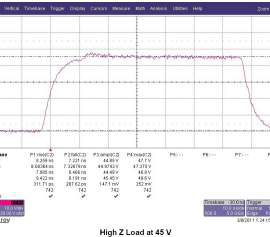
Option AT45 - 45V High and Low Impedance
| Amplitude | 4 V - 45 V |
| Resolution | 20 mV |
| Accuracy | +/-1.5% |
| Rise Time (10%-90%) | < 2 ns into 50 Ω (typ) < 9 ns into Hi-Z (typ) |
| Fall Time (90%-10%) | < 9 ns into 50 Ω (typ) < 9 ns into Hi-Z (typ) |
| Frequency (Internal & External) | DC – 100 kHz |
| Overshoot | < 35% Typical for Fast Rise Time |
| Polarity | High Impedance Mode: Active High or Active Low Low Impedance (50 Ω) Mode: Active High Only |
| Pulse Width Range | High Impedance Mode: 10 ns to DC Low Impedance (50 Ω) Mode: 10 ns to 10 seconds |
| Max Current | 35 mA (Hi-Z @ 10 ms width) 900 mA (50 Ω @ 10 ms width) |
9Optical Inputs / Outputs & Other Options
Option L82 or Option L130 - Optical Outputs
| Wavelength | 820 nm or 1300 nm |
| Maximum Signal Rate | 5 MBd |
| Maximum Link Dist. | 1.5 km |
| Connector Type | ST |
Option IL82 or Option IL130 - Optical Inputs
| Wavelength | 820 nm or 1300 nm |
| Maximum Signal Rate | 5 MBd |
| Maximum Link Dist. | 1.5 km |
| Connector Type | ST |
| Insertion Delay | < 300 ns |
| Jitter | < 1.4 ns RMS |
Additional Options
| DT15 | Dual Trigger. Enable Gate Input to act as second trigger |
| COM | Extended Communications – Adds Ethernet & GPIB |
| EU | Replace North American Cord with European Cord |
10Memory & Connectivity
| Memory Storage | 16 Memory Location |
| USB | USB 2.0 Standard |
| RS-232 | DE-9F Connector using RS-232 Communications Standard |
| External Clock In | 10 MHz – 100 MHz user selectable in discrete values |
| External Clock Out | To or Ref out (10 to 100 MHz) user selectable in discrete values |
11Physical & Environmental
| Dimensions | 10.5” x 8.25” x 5.5” [267 x 210 x 140 mm] |
| Weight | 8 lbs [3.6 kg] |
| Power | 100 - 240 VAC 50/60 Hz < 3 A |
| Fuse | 3.15 A, 250 V Time-lag (Qty 2) |
| Operating Temp | 32 - 104°F [0 - 40°C] |
| Transportation & Storage Temp | -40 - 158°F [-40 - 70°C] |