1Overview
The PCX-7500 is an air-cooled, high-power current source designed to drive laser diodes, bars, and arrays. The output current can be set from 10 A to 450 A, with compliance voltage dependent on the model of the system. The pulse width is adjustable between 4 µs and 5,000 µs, with a repetition rate of 8 Hz to 10,000 Hz.
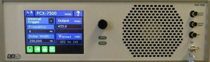
The unit is operated through intuitive front panel controls. The color QVGA LCD provides immediate visual confirmation of all operating parameters, including pulsed current set points, internal trigger pulse width, internal trigger frequency, and error or fault messages. Directed Energy, Inc. is a division of Berkeley Nucleonics, and the PCX-7500 ships from San Rafael, California with one support path.
2How It Works
The laser diode connects to the PCX-7500 through a low impedance strip line cable, designed to preserve the fidelity of high-speed current pulses. The output connector is interlocked, so the PCX-7500 is disabled when the connector is removed. All specifications are measured with a low inductance strip line interconnect cable to the laser diode, with less than 4 nH total inductance.
For automated applications, complete control of the instrument is provided through RS-232, USB, and Ethernet computer interfaces. Up to four system configurations may be stored in internal non-volatile memory, providing instant recall of frequently-used configurations.
Output current pulse, 450 A at 73 V compliance
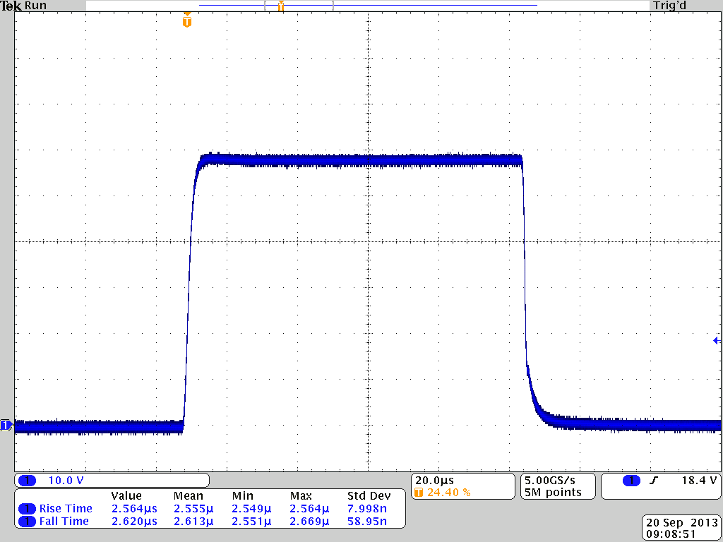
At full output, the source delivers a clean, flat-topped current pulse into a high-compliance diode load. The captured rise and fall times are well under the 7 µs specification, with low overshoot at the leading edge.
Output current pulse, 10 A at 12 V compliance
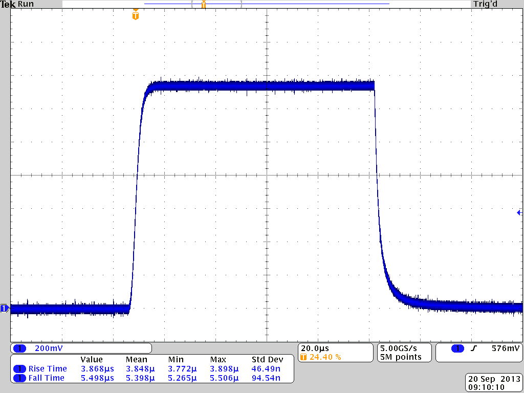
At low output current into a lower-compliance load, the pulse shape stays well controlled. Setpoint resolution is 0.1 A and setpoint accuracy is within 1 percent of full scale across the operating range.
3Specifications
Pulse Amplitude
| Parameter | Specification |
|---|---|
| Output current range | 10 A to 450 A |
| Setpoint resolution | 0.1 A |
| Setpoint accuracy | ±1 % of full scale current |
| Current overshoot | < 2 % |
| Current rise/fall time | ≤ 7 µs |
| Polarity | Positive |
| Compliance voltage | Depends on model (see Available Models) |
| Maximum output power | Up to 1000 W, depends on model |
Internal Trigger
| Parameter | Specification |
|---|---|
| Frequency range | 8 Hz to 10,000 Hz |
| Frequency resolution | 1 Hz between 8 Hz and 299 Hz; 100 Hz between 300 Hz and 10,000 Hz |
| Frequency accuracy | ±1 % |
| Cycle-to-cycle jitter, Tjit(cc) | ≤ 0.025 µs |
| Pulse width range | 4 µs to 5,000 µs |
| Pulse width resolution | 32 µs between 8 Hz and 30 Hz; 8.0 µs between 31 Hz and 122 Hz; 2.0 µs between 123 Hz and 500 Hz; 0.5 µs between 501 Hz and 10,000 Hz |
| Pulse width accuracy | ±0.5 µs |
External Trigger
| Parameter | Specification |
|---|---|
| Frequency range | ≤ 10,000 Hz |
| Input voltage levels | 0 V, output off; 5 V, output on |
| Trigger pulse width | 5 µs to 5,000 µs |
| Delay (external to output) | ≤ 1 µs (typical) |
| Termination impedance | 50 Ω or 10,000 Ω |
| Connector | BNC |
Power
| Parameter | Specification |
|---|---|
| Voltage requirements | 100 VAC to 120 VAC ±10 %; 220 VAC to 240 VAC ±10 % |
| Line frequency | 50 Hz to 60 Hz |
| Power requirements | 1800 W |
| Connector type | IEC 320-C19 |
General
| Parameter | Specification |
|---|---|
| Size (H x W x D) | 15 cm x 44 cm x 54 cm |
| Weight | ~ 20 kg |
| Operating temperature | 15° C to 35° C |
| Cooling | Air cooled |
4Available Models
The PCX-7500 is offered in sixteen models, each rated for a compliance voltage band and a maximum output power. Select the model whose compliance voltage covers the forward voltage of the diode load.
| Model | Compliance voltage1 | Maximum output power1 |
|---|---|---|
| PCX-7500-5 | 0 V to 5 V | 100 W |
| PCX-7500-12 | 5 V to 12 V | 225 W |
| PCX-7500-17 | 12 V to 17 V | 400 W |
| PCX-7500-24 | 17 V to 24 V | 450 W |
| PCX-7500-30 | 24 V to 30 V | 600 W |
| PCX-7500-38 | 30 V to 38 V | 700 W |
| PCX-7500-48 | 38 V to 48 V | 700 W |
| PCX-7500-54 | 48 V to 54 V | 700 W |
| PCX-7500-62 | 54 V to 62 V | 700 W |
| PCX-7500-66 | 62 V to 66 V | 700 W |
| PCX-7500-73 | 66 V to 73 V | 700 W |
| PCX-7500-78 | 73 V to 78 V | 750 W |
| PCX-7500-86 | 78 V to 86 V | 800 W |
| PCX-7500-94 | 86 V to 94 V | 900 W |
| PCX-7500-102 | 94 V to 102 V | 950 W |
| PCX-7500-110 | 102 V to 110 V | 1000 W |
1 Operation of an instrument outside of the listed compliance voltage and maximum power limits can cause permanent damage to the instrument and/or load. See the SOA graphs in the manual for more information.
5Output Protection & Safety
The output connector is interlocked, so the PCX-7500 is disabled when the connector is removed. Each model has a defined safe operating area set by its compliance voltage band and maximum output power. The source must be operated within these limits, which keep the instrument and the connected diode within thermal and electrical bounds.
6Control & Interfaces
The PCX-7500 may be operated through its front panel controls or through its computer interfaces. Conveniently located front panel BNC connectors allow the unit to be externally triggered and synchronized for specialized interconnected equipment applications. The trigger input impedance is selectable to either 50 Ω or 10,000 Ω. The synchronization output pulse is synchronized to the leading edge of the output current pulse and is active with internal or external triggers.
Output Connector
| Parameter | Specification |
|---|---|
| Type | DB37 pin female |
| Pin 1 to 16 | Out + |
| Pin 20 to 35 | Out − |
| Pin 18 and 19 | Cable present loopback |
| All other pins | Not connected |
Control Signals
| Parameter | Specification |
|---|---|
| Sync termination | 50 Ω |
| Sync connector | BNC |
| Current monitor | 0 to 800 mV; 100 A output current = 170 mV (typical) |
| Current monitor termination | 50 Ω |
| Current monitor connector | BNC |
| Voltage monitor | 0 to 920 mV; 50 V output = 375 mV (typical) |
| Voltage monitor termination | 1 MΩ |
| Voltage monitor connector | BNC |
Computer Interfaces
| Parameter | Specification |
|---|---|
| Supported interfaces | RS-232, Ethernet, USB |
| USB driver support | Windows 8, Windows 7, Windows XP, Linux, and Mac OS X |
7Applications
The PCX-7500 drives high-current optical loads where pulse fidelity and a wide compliance range matter. Typical uses include:
- Laser diode bars and arrays. Peak currents to 450 A for high-power diode drive across a 5 V to 110 V compliance range.
- QCW pumping. Quasi-CW current delivery with pulse widths from 4 µs to 5,000 µs at rates up to 10 kHz.
- Diode test and characterization. Setpoint accuracy within 1 percent of full scale, with current and voltage monitor outputs for measurement.
8Ordering Information
| Part number | Description |
|---|---|
| PCX-7500-xxx | Pulsed current source; see Available Models for the sixteen voltage and power variants |
| Output strip line cable | Low inductance output cable (part number TBD per PDF) |
| Laser output PCBA | Laser output PCBA (part number TBD per PDF) |