1. General Safety Summary
Review the following safety precautions to avoid injury and prevent damage to this product or any products connected to it. To avoid potential hazards, use this product only as specified. Only qualified personnel should perform service procedures.
To Avoid Fire or Personal Injury
- Use Proper Power Cord. Use only the power cord specified for this product and certified for the country of use.
- Ground the Product. This product is grounded through the grounding conductor of the power cord. To avoid electric shock, the grounding conductor must be connected to earth ground. Before making connections to the input or output terminals of the product, ensure that the product is properly grounded.
- Observe All Terminal Ratings. To avoid fire or shock hazard, observe all ratings and markings on the product. Consult the product manual for further ratings information before making connections to the product.
- Power Disconnect. The power cord provides Mains disconnect.
- Do Not Operate Without Covers. Do not operate this product with covers or panels removed.
- Do Not Operate With Suspected Failures. If you suspect that there is damage to this product, have it inspected by qualified service personnel.
- Avoid Exposed Circuitry. Do not touch exposed connections and components when power is present.
- Do Not Operate in Wet/Damp Conditions. Do not operate in wet or damp conditions.
- Do Not Operate in an Explosive Atmosphere.
- Keep Product Surfaces Clean and Dry.
- Provide Proper Ventilation. Refer to the manual's installation instructions for details on installing the product so it has proper ventilation.
Safety Requirements and Symbols
This section contains information and warnings that must be observed to keep the instrument operating in a correct and safe condition. You are required to follow generally accepted safety procedures in addition to the safety precautions specified in this section.
Safety Symbols
Where the following symbols appear on the instrument front or rear panels, or in this manual, they alert you to important safety considerations.
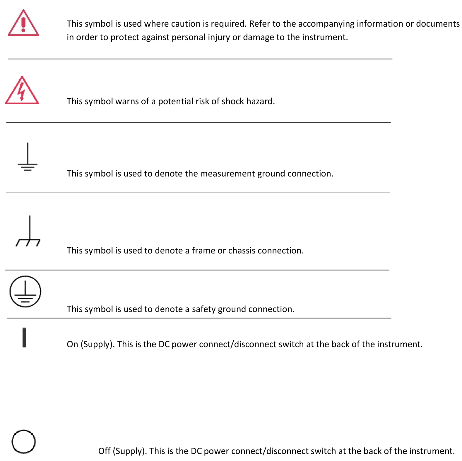
CAT I. Installation (Overvoltage) Category rating per EN 61010-1 safety standard is applicable for the instrument front panel measuring terminals. CAT I rated terminals must only be connected to source circuits in which measures are taken to limit transient voltages to an appropriately low level.
2. Operating Environment & Requirements
Operating Environment
The instrument is intended for indoor use and should be operated in a clean, dry environment. Before using this product, ensure that its operating environment is maintained within these parameters.
| Parameter | Specification |
|---|---|
| Temperature | 5 °C to 40 °C |
| Humidity (operating) | 5 % to 80 % RH, maximum wet bulb 29 °C at or below +40 °C (de-rates to 20.6 % RH at +40 °C), non-condensing |
| Humidity (non-operating) | 5 % to 95 % RH, maximum wet bulb 40 °C at or below +60 °C (de-rates to 29.8 % RH at +60 °C), non-condensing |
| Altitude (operating) | Up to 3,000 m (9,842 ft) at or below 25 °C |
AC Power Source
For the External AC Adapter: 100 to 240 VAC (+/- 10%) at 45-66 Hz; Automatic AC voltage selection; Installation Category 300V CAT II. No manual voltage selection is required because the external AC adapter automatically adapts to line voltage.
Power Consumption. < / = 150 watts.
Maintenance
Calibration. The recommended calibration interval is one year. Calibration should be performed by qualified personnel only.
Cleaning. Clean only the exterior of the instrument, using a damp, soft cloth. Do not use chemicals or abrasive elements. Under no circumstances allow moisture to penetrate the instrument.
Abnormal Conditions. Operate the instrument only as intended by the manufacturer. If you suspect the instrument protection has been impaired, disconnect the power cord and secure the instrument against any unintended operation.
Environmental Considerations
This section provides information about the environmental impact of the product.
Product End-of-life Handling
Observe the following guidelines when recycling an instrument or component.
Equipment Recycling. Production of this equipment required the extraction and use of natural resources. The equipment may contain substances that could be harmful to the environment or human health if improperly handled at the product's end of life. In order to avoid release of such substances into the environment and to reduce the use of natural resources, we encourage you to recycle this product in an appropriate system that will ensure that most of the materials are reused or recycled appropriately.

Operating Requirements
Power Supply
Source Voltage and Frequency: 100 to 240 V RMS @ 50-60 Hz.
| Characteristic | Condition | Min | Nom | Max | Units |
|---|---|---|---|---|---|
| Voltage | 45-66 Hertz | 85 | 100-240 | 264 | VRMS |
| Voltage | 360-440 Hertz | 100 | 115 | 132 | VRMS |
| Voltage Wave | All | Sine | |||
| Power Consumption | — | Maximum 150 W, Measured 125 W | |||
| Surge Current | 25 °C | 30 A peak for 5 line cycles, after product has been turned off for at least 30 s | |||
Mechanical Characteristics
| Parameter | Specification |
|---|---|
| Net Weight | 10.5 kg |
| Net Weight with Package | 11.5 kg |
| Overall Dimensions | Height 160 mm, Width 450 mm |
| Dimensions with Package | Height 210 mm, Width 500 mm |
Environmental Characteristics
| Parameter | Specification |
|---|---|
| Temperature | Operating +5 °C to +50 °C (+41 °F to 122 °F) |
| Humidity | Operating 8 % to 90 % relative humidity with a maximum wet bulb temperature of 29 °C at or below +50 °C, non-condensing. Non-operating 5 % to 98 % relative humidity with a maximum wet bulb temperature of 40 °C at or below +60 °C, non-condensing. |
| Altitude | Operating 3,000 m (9,843 feet); non-operating 12,000 m (39,370 feet) |
3. Preface & Package Contents
Preface
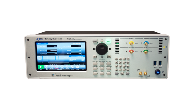
This manual describes the installation and operation of Model 765 instruments Revision B. Basic operations and concepts are presented in this manual. The following instruments are supported by this manual:
- Model 765-2 Rev.B
- Model 765-4 Rev.B
The Model 765 Series offers premium signal integrity with the easiest to use touch screen display interface (SimpleRider). The generation of pulses requires only a few screen touches. The output Voltage can be adjusted up to 5 Volts pk-pk in a window of ±5 Volts with 70 ps edge rate (based on RiderEdge technology) and transitions with minimal overshoot and ringing. Its innovative hardware architecture provides the possibility to generate advanced pulse sequences, such as double pulse or quad pulse, with fully independent timing parameters.
Package Contents
The standard Model 765 package includes the following:
- Model 765-2 or Model 765-4 pulse generator instrument
- Power Cord
- Performance/Calibration Certificate
- Model 765 Introduction and Compliance document
2-4 Channels
The Pulse Generator is available with the basic Dual Channel (765-2) version or with the Quad Channel version (765-4). Each channel may generate pulses with rise time as low as 70 ps, thanks to the RiderEdge amplifier, and frequency repetition rate from mHz to 125 MHz in single pulse mode. By using the Multiple output pulses feature it is also possible to reach a maximum repetition rate of 800 MHz. Output Voltage is fully adjustable up to 5 Volts pk-pk inside a Voltage window of ±5 Volts; the offset is adjustable inside a Voltage window of ±2.5 Volts.
The RiderPulse Generator family can produce Multiple output pulses (double pulse, quad pulse) with independent repetition rate, width, delay, amplitude and polarity. This gives the possibility to use the instrument as a digital delay generator for rescaling, synchronizing, delaying, gating and triggering multiple devices with respect to one unique event.
Trigger, View, Generate and Sync
Trigger events may be generated internally or captured by an external trigger source or remotely from Ethernet or GPIB connections. Trigger In and Trigger Out may be used to synchronize multiple units to obtain several pulses and to provide a solution for Big Physics, Military applications or Semiconductor testing.
Touch Screen Display and Soft Keyboard
The Rider Series delivers a 7" capacitive touch screen display, and the touch-screen friendly SimpleRider software allows users to generate pulses quickly by a few screen touches. The UI ergonomic approach offers multiple ways to operate the instrument with a complementary soft keyboard and a central knob for fine-tuning and adjustments during set up.
SimpleRider Pulse Touch User Interface
All instrument controls and parameters are accessed through an intuitive UI that recalls the simplicity of tablets and modern smart phones. The swipe gesture gives easy access to the output and pulse parameters. A touch-friendly virtual numeric keypad improves the data-entry experience. Model 765 supports the most common interfaces for remote control (Ethernet, GPIB).
- Touch-friendly virtual numeric keypad improves the data-entry experience.
- Time saving shortcuts and intuitive icons simplify your setup also during pulse combination operations.
- Most common interfaces for remote control (Ethernet, GPIB) for easy customized instrument programming.
Recommended Accessories
| Item | Description |
|---|---|
| RM KIT | Rack Mount Kit |
| SSD KIT | SSD Solid State Drive |
| WAR EXT | Warranty Extension |
| CAL. CERT | Certification of Calibration |
Power the Instrument On and Off
Power On
- Insert the AC power cord into the power receptacle on the rear panel.
- Use the front-panel power button to power on the instrument.
- Wait until the system shows the Windows desktop.
- The Model 765 software will start automatically.
Power Off
- Close the application in use (Exit).
- Press the front-panel power button to power off the instrument.
Protect Your Instrument from Misuse
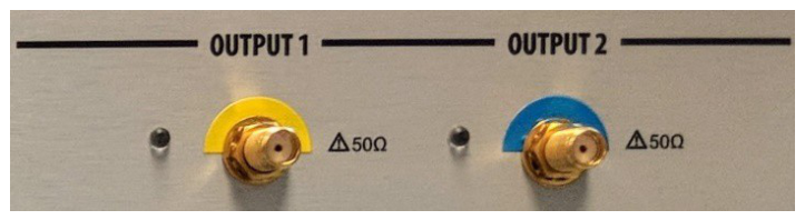
Check Input and Output Connectors
When connecting a cable, be sure to distinguish the input connector from the output connectors to avoid making the wrong connection. The instrument has both input and output connectors on the front panel.
4. Getting the Software & Remote Control
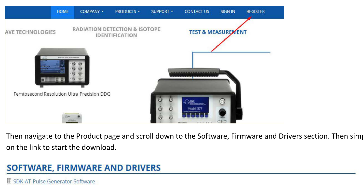
Obtaining the Latest Version Releases
The latest version of an optional application that you ordered with your instrument may not be installed on your instrument. The following download location is a fast and easy way to get the latest software version. To download the latest version of software, register on the website: go to the home page of the Berkeley Nucleonics website (www.berkeleynucleonics.com), press the Register button in the upper right of your screen. Then navigate to the Product page and scroll down to the Software, Firmware and Drivers section. Then simply click on the link to start the download.
Install the Model 765 Pulse Generator Application
If your instrument has already installed another version of the Pulse Generator app, you must first uninstall it.
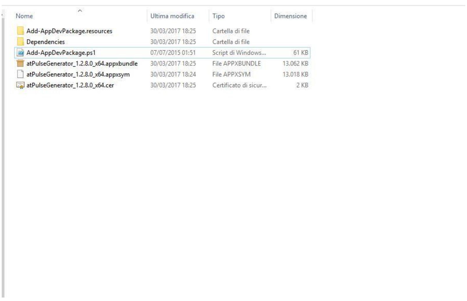
- Download the Model 765 Pulse Generator setup package from the Berkeley Nucleonics website and decompress it to the instrument's local disk.
- Right click on the
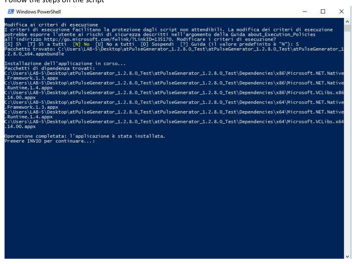
Add-AppDevPackage.ps1file and select "Run with PowerShell". - Follow the steps in the script.
- When the application has been installed, press Return to continue.
Remote Control
You can connect your instrument to a network for printing, file sharing, and Internet access, among other functions. Consult with your network administrator and use the standard Windows utilities to configure the instrument for your network. The instrument can be controlled using the VXI-11 (LAN) protocol. It allows you to control the instrument remotely by using SCPI commands. Please refer to the Model 765 programmer manual for a complete description about all available commands. You can follow the next steps to communicate with your Model 765 Series instrument.
NI-VISA
VISA provides the programming interface between the hardware and development environments such as Visual Studio .NET, LabVIEW, LabWindows/CVI, Measurement Studio for Microsoft Visual Studio and MatLab. NI-VISA is the National Instruments implementation of the VISA I/O standard. NI-VISA includes software libraries, interactive utilities such as NI I/O Trace and the VISA Interactive Control, and configuration programs through Measurement & Automation Explorer for all your development needs.
- Connect your LAN cable to the instrument.
- Install NI-VISA. On the Client-PC you must install the latest NI-VISA package.
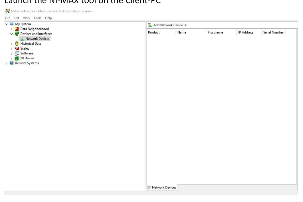
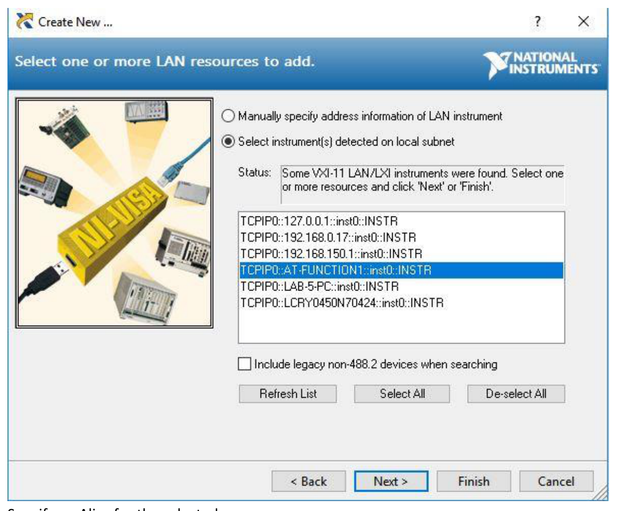
- Launch the NI-MAX tool on the Client-PC, then press Add Network Device → VISA TCP/IP Resource.
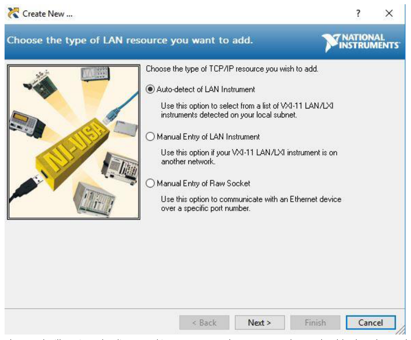
- Select Auto-detect of LAN Instrument.
- The panel will retrieve the discovered instruments on the LAN; select the Model 765 series one.
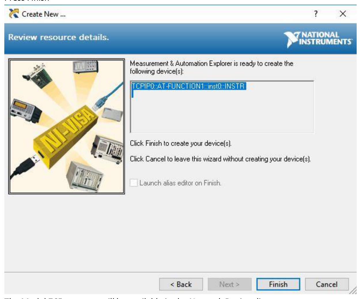
- Specify an Alias for the selected resource.
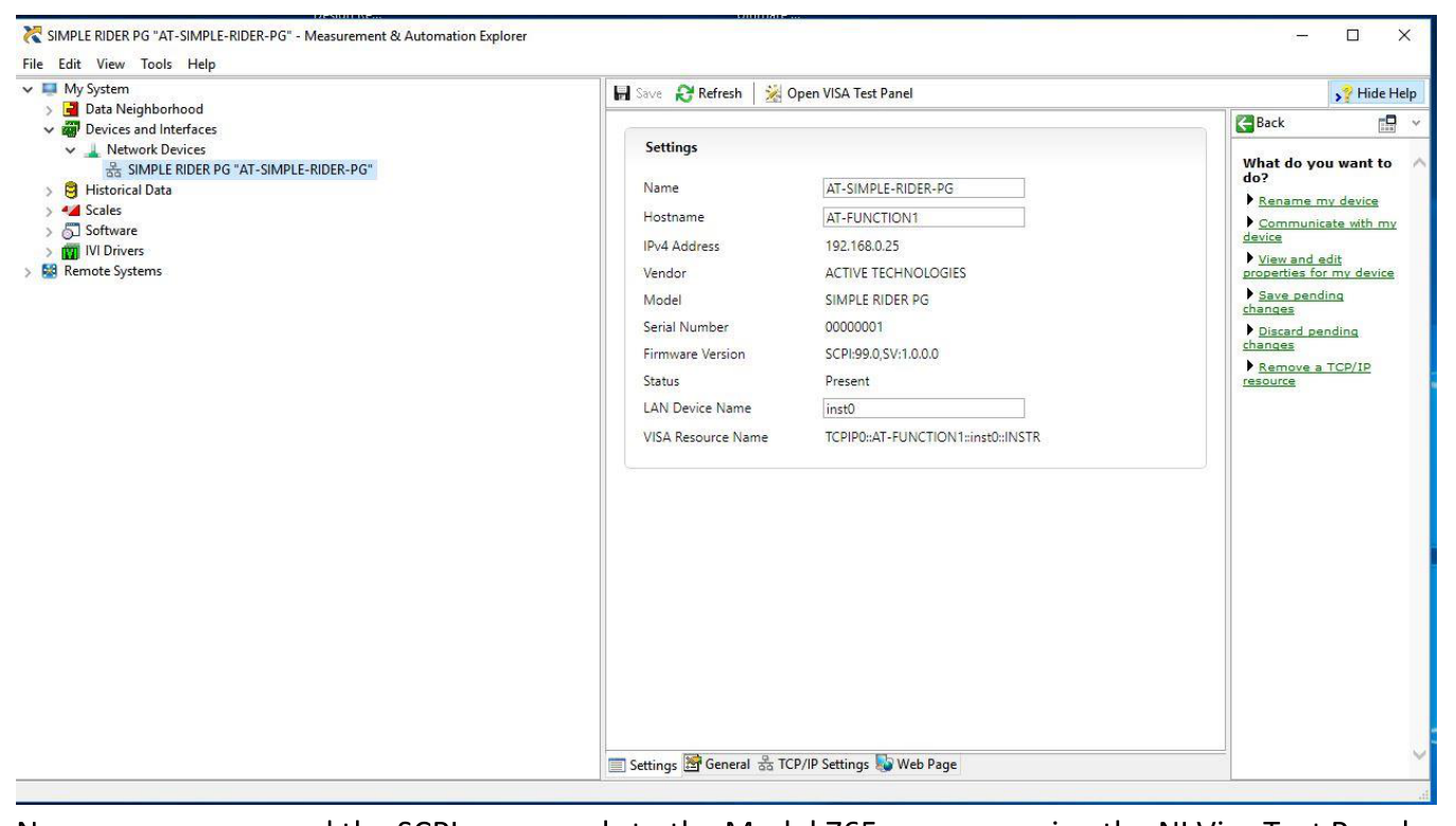
- Press Finish. The Model 765 resource will be available in the Network Devices list.

AT Instrument Communicator
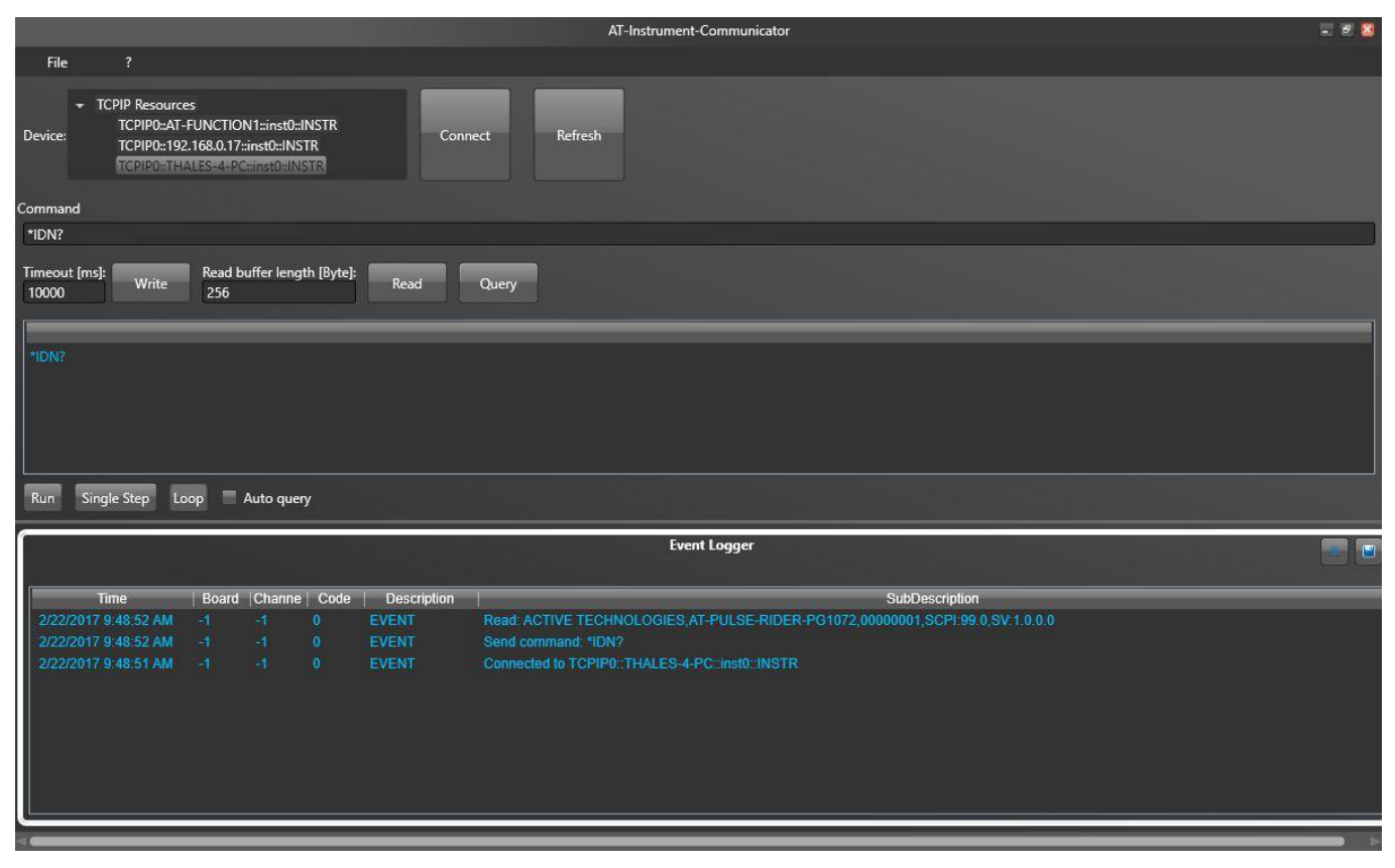
The instrument VXI-11 LAN Server provides software connectivity between your instrument and remote PCs over an Ethernet LAN. The AT-Instrument-Communicator software is a client-side component tool that uses NI-VISA on each remote PC; you must install a copy of NI-VISA to make use of this client-side component (please follow the Prerequisite steps). On the Client-PC (IP Address) or Model 765 instrument (Local Host), launch the AT-Instrument-Communicator tool.
- On the Client-PC, launch the AT Instrument Communicator setup and install the software.
- Select the Model 765 resource on the Device list.
- Press the Connect button.
- If the instrument connection is established, the SCPI command button will be enabled.
- Write
*IDN?in the command. - Press the Query button.
- In the Event Logger list, the instrument should respond like this:
ACTIVE TECHNOLOGIES, AT-PULSE-RIDER PG1072 00000001, SCPI 99.0, SV 1.0.0, where 00000001 is the serial number, SCPI 99.0 is the SCPI command version and SV 1.0.0 is the software version. - A command script is a list of SCPI commands (one command for each line) saved in a txt file; you can send a command script using the File → Load Script menu item.
- Refer to the SCPI programmer manual for a complete list of all available commands.
5. Instrument Overview
Front Panel
The numbered callouts on this image correspond with the following descriptions. The front panel carries the 7" capacitive touch screen, the soft keyboard and rotary knob, the numeric keypad, the single-ended analog outputs, the Trigger IN / Trigger OUT connectors, the USB 3.0 ports and the power on/off button.
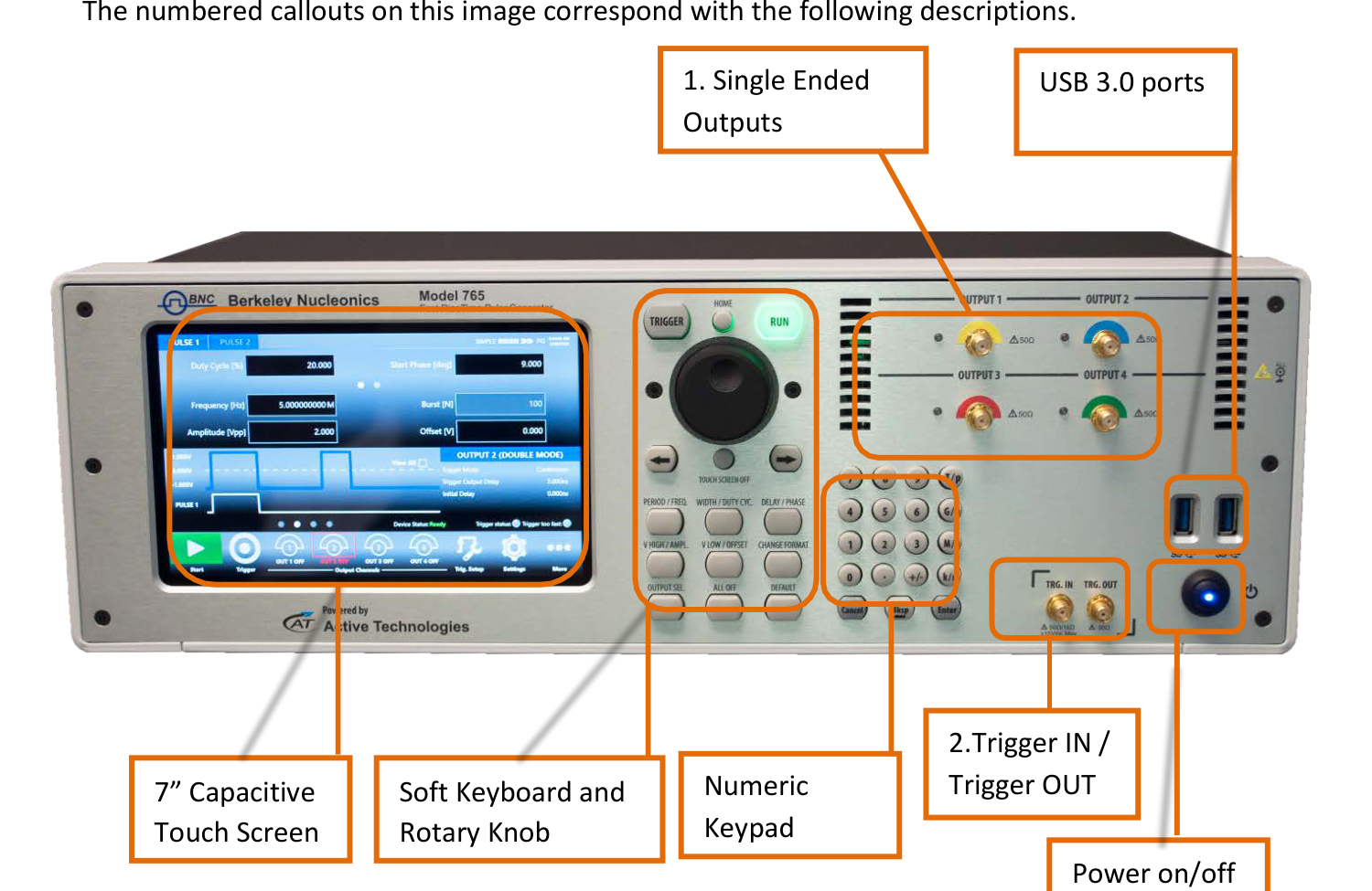
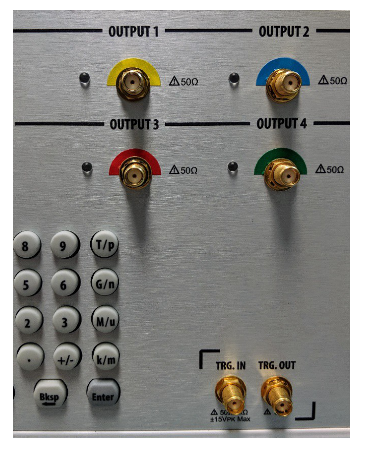
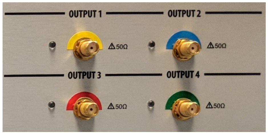
1. Analog Outputs.
- OUTPUT 1: Single Ended DC Coupled Analog output 1 (SMA connector).
- OUTPUT 2: Single Ended DC Coupled Analog output 2 (SMA connector).
- OUTPUT 3: Single Ended DC Coupled Analog output 3 (SMA connector), PG1074 only.
- OUTPUT 4: Single Ended DC Coupled Analog output 4 (SMA connector), PG1074 only.
The DC coupled is a single output with 50 Ohm output impedance; in case you need a differential output you should use the OUTPUT 1 and the OUTPUT 2 and set them in the SimpleRider UI as positive and negative pulses.
2. Trigger Input / Output. TRG.IN is an SMA input connector for Trigger IN with a programmable impedance of 50 Ohm or 1 k Ohm and a programmable threshold level in the range -10 V to 10 V. TRG.OUT is an SMA output connector for Trigger OUT; the trigger output impedance is 50 Ohm and the voltage range on open load is from 1.8 V to 3.3 V.
Rear Panel
The callouts on this image correspond with the following descriptions.
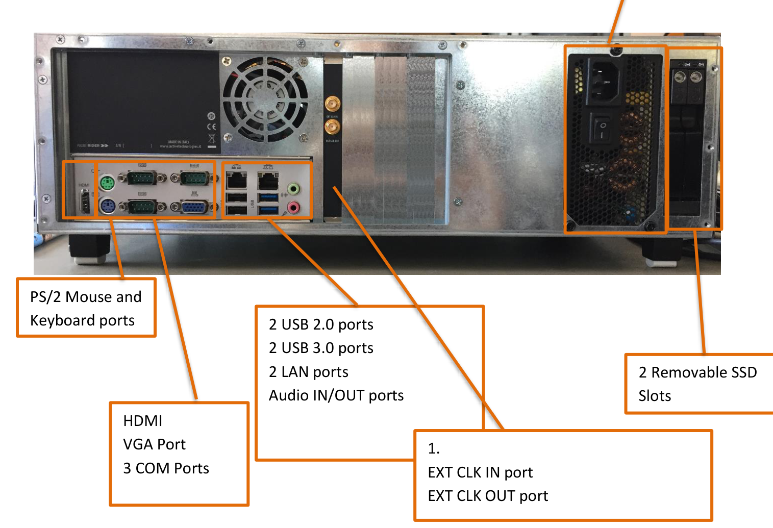
External Clock. EXT. CLK IN (SMA) lets the Model 765 use an external clock source to generate the instrument time base, synchronizing the generator with an external clock. EXT. CLK OUT (SMA) outputs the internal 10 MHz reference clock when the source is internal, or the Ext.Clk.IN value when the source is external. (verify: the internal 10 MHz reference value for EXT CLK OUT was not restated verbatim on the rear-panel pages and should be confirmed against the datasheet.)
6. Getting Started with Model 765
Instrument Control
The Model 765 includes a 7" capacitive touch screen and the SimpleRider touch user interface based on a Microsoft Windows platform. You can control instrument operations using the touchscreen, the front-panel soft key controls, or a keyboard and mouse.
SimpleRider UI is designed for touch to drive simplicity in operating with a pulse generator, by optimizing today's modern technique, used on Tablet or smart phones, of capacitive touch screen display. All important instrument controls and settings are always one touch away: swipe gesture to change the channel and pulse selection and to have access to the modulation parameters (i.e. multiple pulses easily using the touch-combiner), the touch-friendly virtual numeric keyboard to change parameter values on the fly.
Front Panel Buttons
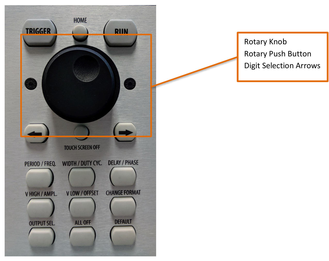
Most of the buttons you use with Model 765 are virtual ones on the touchscreen, but a few physical buttons control basic functions, such as setting the pulse amplitude, offset, delay, width etc. A physical numeric keypad is available on the front-panel and it can be used instead of the virtual numeric pad. A useful central knob is available for fine-tuning and adjustments during the on-the-fly set up operation.
- Rotary knob. Changes the value in a continuous, analog fashion.
- Push button rotary knob. Changes the value increment between Coarse and Fine adjustment.
- Digit selection arrows. The right and left arrow keys move the selected digit.
- Delta increment. You can keep the rotating knob pressed and rotate it on the right or on the left to change the Delta increment.
| Button Name | Function |
|---|---|
| HOME | If you are in a software sub-menu page, use this button to return to the main page. |
| TRIGGER | Use this button to send an internal trigger to the instrument. |
| RUN | Use this button to start and stop the pulse generation. When the button led is green, it means that the instrument is in running (or armed, ready to receive the trigger signal). |
| LEFT ARROW | Once the virtual numeric keypad will be opened, use this button to move the digit selection cursor. |
| RIGHT ARROW | Once the virtual numeric keypad will be opened, use this button to move the right digit selection cursor. |
| TOUCH SCREEN OFF | Use this button to disable the touch screen. |
| PERIOD / FREQ. | Use this button to set the period or the frequency of the pulse waveform. |
| WIDTH / DUTY CYC. | Use this button to set the width or the duty cycle of the pulse waveform. |
| DELAY / PHASE | Use this button to set the delay or the phase of the pulse waveform. |
| V HIGH / AMPL. | Use this button to set the high voltage level or the amplitude of the pulse waveform. |
| V LOW / OFFSET | Use this button to set the low voltage level or the offset of the pulse waveform. |
| CHANGE FORMAT | Use this button to change the format of the data entry between Format A (Period, Width, Delay, Phase, Voltage Level High, Voltage Level Low) and Format B (Frequency, Duty Cycle, Phase, Amplitude, Offset). Some pulse parameters can be controlled in alternate formats. For example, displays and controls the time interval between pulses. If you press this button while Period is selected, the display will change to Frequency. Now, you can control and read back the frequency at which pulses are output. |
| OUTPUT SEL. | Use this button to change the output selection in the user interface. |
| ALL OFF | Use this button to turn off all the outputs. |
| DEFAULT | Use this button to restore the default settings. |
Front Panel Numeric Keypad
The physical numeric keypad lets you set the pulse parameter value and its measure unit. Use the touch panel to select the pulse parameter. Each number pressed is shown on the display, and the Bksp key deletes erroneous key presses. The [+/-] key toggles the sign of the number being entered and may be pressed at any time before terminating entry. After the sign and numeric portion are entered, terminate entry with the appropriate multiplier by pressing one of the four unit-measure keys at the right of the keypad. When you select a parameter, pressing the unit measure button automatically sets the available range linked to the parameter.
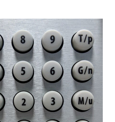
| Unit Measure Range Button | Unit Measure Range |
|---|---|
| T/p | Tera / pico |
| G/n | Giga / nano |
| M/u | Mega / micro |
| k/m | Kilo / milli |
As an example when you select a Frequency parameter and you press k/m the unit measure range that will be inserted is kHz; if you press M/u it will be inserted MHz, if you press M/u nothing will happen because that range is not available for the selected parameter. If more than one unit-measure range is available for a selected parameter (for example Mega and Micro), toggling the range button M/u switches the range accordingly between Mega and Micro.
7. Output and Pulse Definition
The term Output Channel as used in this user manual refers to the analog signal at the SMA output connectors (labels OUTPUT 1, OUTPUT 2, OUTPUT 3, OUTPUT4) on the front panel.
The Output Channel parameters are Voltage High / Amplitude [V], Voltage Low / Offset [V], and Period [s] / Frequency [Hz].
The term Pulse refers to the logical pulse that is internally generated by the digital core of the Model 765 instrument and that is used to compose the analog Output channel signal. Up to four digital pulses called PULSE1, PULSE2, PULSE3 and PULSE4 are available for each Output channel through the SimpleRider user interface; this feature lets you generate Multiple Pulses at the output channel. The Pulse parameters are Width [s] / Duty Cycle [%] and Delay [s] / Phase [degree].
Output Channel Parameters
Vertical Parameters
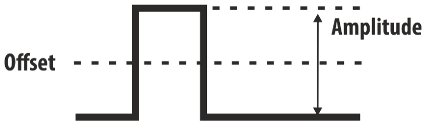
The Model 765 default format provides the control of the vertical (voltage) parameters of the Output channel. Voltage High [V] controls the output high voltage level; Voltage Low [V] controls the output low voltage level. The output signal levels indicated by the SimpleRider UI will be delivered into 50 Ohm load. Pressing the Change Format front panel or touch button will change the display of those parameters to Amplitude [V] and Offset [V]. Amplitude [Vpp] is the difference between the active and the quiescent levels of the Output pulse. Offset [V] is the quiescent level of the signal of the Output channel.

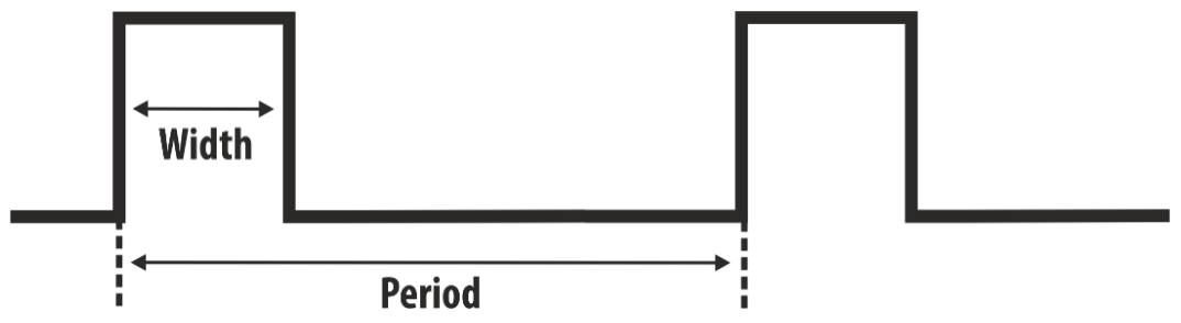
Period / Frequency
Period [s] parameter defines the time between Output pulses in Continuous, Burst and Gated mode. Pressing the Change Format front panel or touch button will change the display of that parameter to Frequency. Frequency [Hz] controls the frequency of Output pulses in Continuous, Burst and Gated mode.
Pulse Parameters
Width / Duty Cycle
The time duration of the Pulse is controlled by the Width / Duty Cycle parameter. The Width [s] defines the time interval during the Pulse N is in the active state. Pressing the Change Format button, the mode of control over the duration of the Pulse N will change to Duty Cycle. The Duty Cycle [%] defines the percentage of the Period over which the Pulse N is in the active state.
Delay / Phase
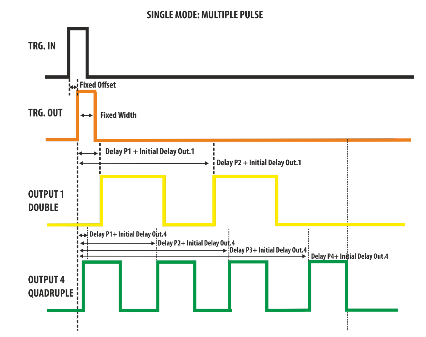
The Delay [s] parameter defines the time interval from the Trigger Output to the Pulse N, excluding an initial output channel delay that can be set in the Settings page. In Single Pulse mode the Output 1 and Output 2 signals are created by Pulse1/Output1 and Pulse1/Output2.
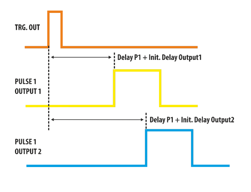
If you press the Change Format button, the displayed name for the Delay parameter will change to Phase. Phase [degree] provides position control in a manner proportional to Period, with 0 degree corresponding to the minimum Delay setting. This phase angle is maintained as Period is varied, so once Phase has been set, the Pulse Delay = (Phase / 360) × Period.
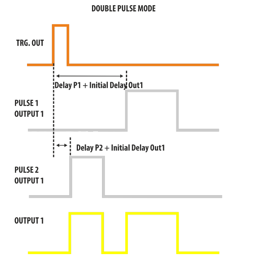
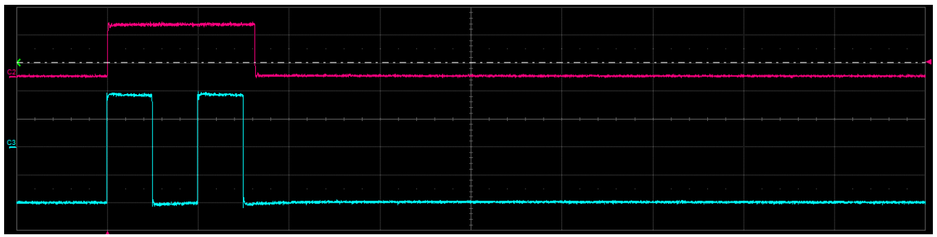
In Double Pulse mode the Output 1 signal is created by the logical OR combination of Pulse1/Output1 and Pulse2/Output1.
Parameter Conflicts
The following conditions must be true in order to avoid conflicts:
- Voltage High > Voltage Low.
- Width [s] + Delay [s] < Period [s].
Parameter Limits
| Parameter | Min | Max |
|---|---|---|
| Voltage High | -5.0 V | +5.0 V |
| Voltage Low | -5.0 V | +5.0 V |
| Amplitude | -2.5 V | +2.5 V |
| Offset | -2.5 V | +2.5 V |
| Width | 300 ps | 8 s |
| Duty Cycle | 1 % | 99.9 % |
| Period | 5 ns | 8 s |
| Frequency | 0.125 Hz | 200 MHz |
| Delay | 0 s | 8 s |
| Phase | 0 degree | 360 degree |
| Burst N | 1 | 4294967295 |
Multiple Pulses Operation
Four digital pulses are available on each Output and they are logically combined by an OR operation, giving you the possibility to generate Multiple Pulses at the Output SMA connector reaching up to 800 MHz repetition rate. In Continuous and Single Trigger modes, when the Multiple Pulse feature is turned off, one Output Pulse follows each Trigger Output.
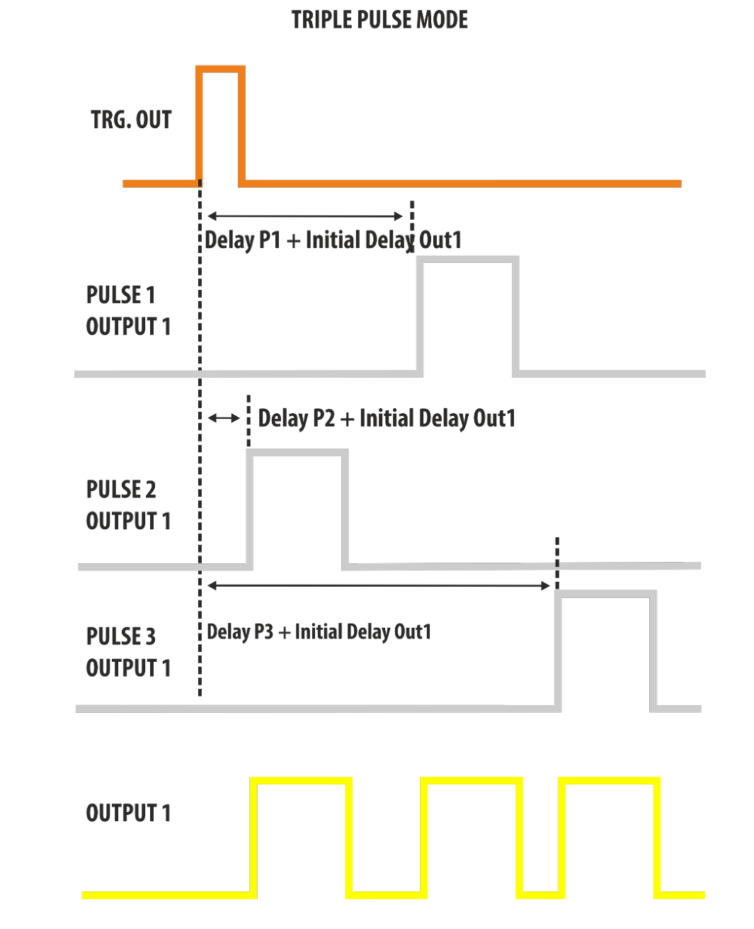
By pressing the Settings button on the command bar you access the Output Mode selection. In Continuous and Single modes you can have two, three or four output pulses for each Trigger Output. On the right of the page, click the arrow icon to expand or collapse the picture that graphically explains the output composition in relationship to the pulses.
In Triple Pulse Mode, the Output signal will be the logical OR combination of the PULSE1, PULSE2 and PULSE3.
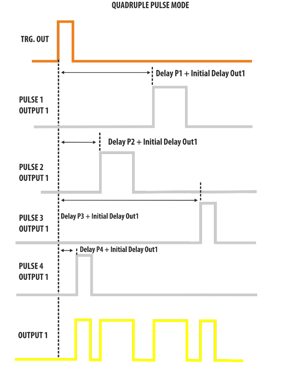
In Quadruple Pulse Mode, the Output signal will be the logical OR combination of the PULSE1, PULSE2, PULSE3 and PULSE4.
Hint: How to Generate a Clock
It is possible to create a clock with a frequency greater than 200 MHz using the multiple pulse mode through the following steps:
- Calculate the clock Period. PeriodClock = 1 / Frequency.
- Find the lowest value of N that satisfies N × PeriodClock > 8 ns, with N = 2, 3, 4.
- Select Single Pulse mode and set Width = PeriodClock / 2, Delay = 0 ns, Period = N × PeriodClock.
- Select the Multiple pulse mode that corresponds to the N value (2 = Double, 3 = Triple, 4 = Quadruple).
Example: I need to generate a clock frequency of 333 MHz.
- PeriodClock = 1 / 333 MHz = 3.003 ns.
- N = 2 → 2 × 3.003 ns > 8 ns? No.
- N = 3 → 3 × 3.003 ns > 8 ns? Yes. The pulse mode will be Triple Pulse Mode.
- Select Single Mode, Width = PeriodClock / 2 = 1.501 ns, Delay = 0 ns, Period = N × PeriodClock = 9.009 ns.
- Open the Channel Settings and select Triple Pulse Mode.
- Press Run.

8. Trigger Controls
The Model 765 Outputs are driven from a common timebase and the channel outputs are referenced to the same trigger. This means that the output channels share the same trigger modes but can have different period, width and delay.
Trigger Output
The signal at the Rider Pulse TRG.OUT connector is a selectable positive-going or negative-going pulse, synchronized with the TRG.IN signal and the Model 765 internal timebase in Single, Gated and Burst mode. In Continuous mode the TRG.OUT signal is synchronized with the selected output and the internal timebase. The Trigger Output Delay parameter is relative to the signal's leading edge. The width of the Trigger Output is dependent upon the selected Trigger Mode, its amplitude is programmable from 0.9 V to 1.65 V into a 50 Ohm load.
Trigger Input
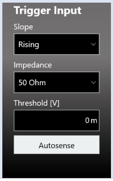
The Model 765 can be adjusted to trigger on any signal connected to the TRG.IN connector whose amplitude is greater than 20 mV. Trigger pulses as narrow as 1 ns can be detected. The impedance of the Trigger Input can be programmed to either 1 k Ohm or 50 Ohm. The signal levels at the TRG.IN must not exceed ±10 V into 1 k Ohm and ±3.5 V into 50 Ohm; the threshold level can be programmed in the ±8 V range with 4 mV steps. Pressing the button "Autosense", the instrument can automatically measure the threshold of the signal applied to the Trigger In port.
In Single, Burst and Gated mode the Frequency counter measures the frequency of the signal at the TRG.IN and displays the result of the measurement in the Trigger Setup window. In Single, Burst and Gated mode the software trigger (trigger button) is always active independently from the selected trigger source.

Trigger Modes
The Model 765 has four trigger operating characteristics: Single, Burst, Gated and Continuous.
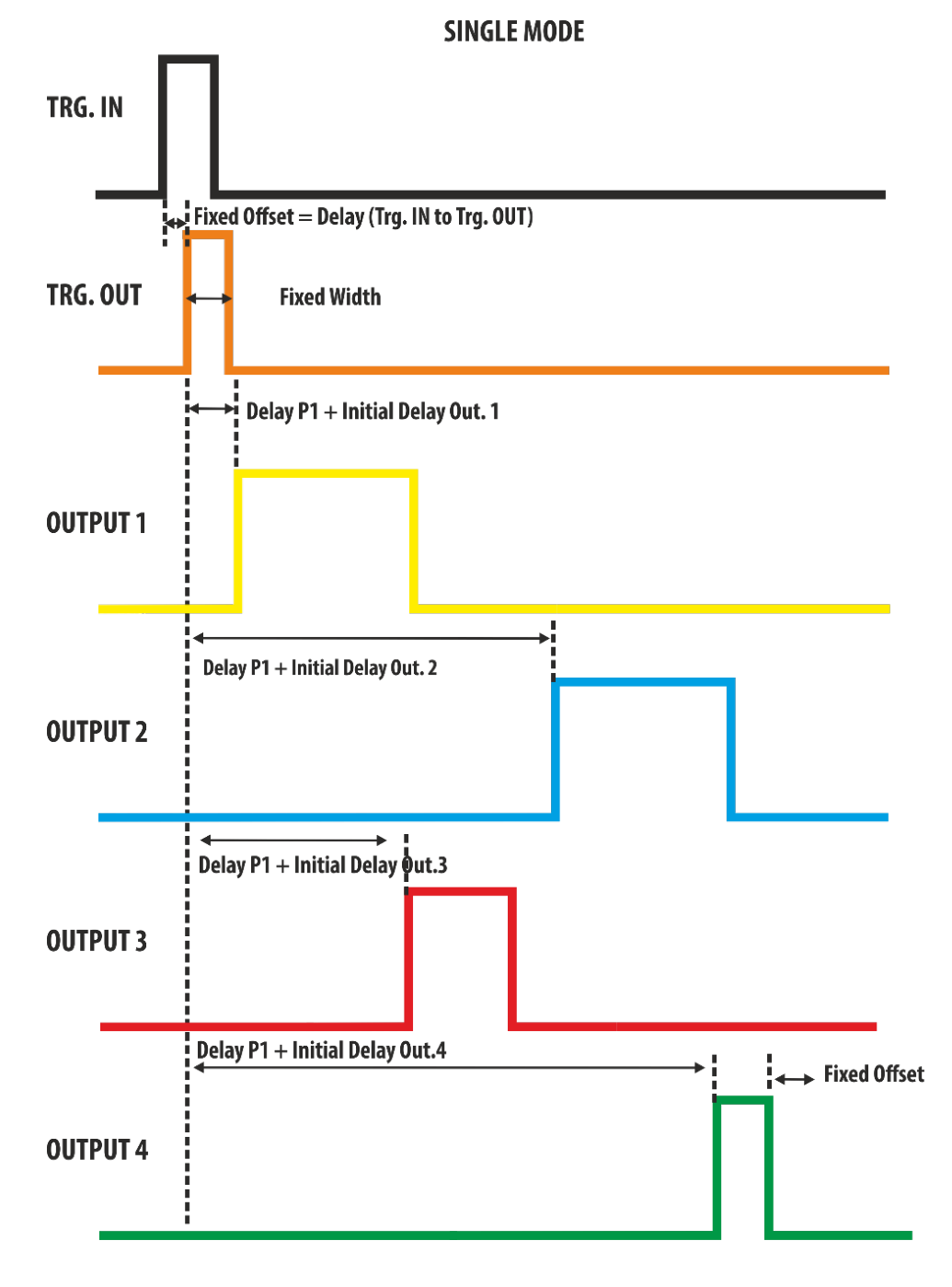
Single Mode
In Single Mode the Trigger IN source can be sent externally using the TRG.IN connector or internally using the front panel button, SCPI command and timer. The Trigger Output signal is linked to one of the available Outputs using the Trigger Output → Trigger Source dropdown list. The Trigger IN signals starts the Model 765 timebase and one TRG.OUT signal follows each trigger that is detected on the selected output channel with a delay below 100 ns.
- If the Output channel linked to the Trigger Output Source is disabled (OFF state), the TRG.OUT signal will not follow that output. Its state will be 0 or 1 depending on the selected polarity.
- If all channels will be disabled, the TRG.OUT signal state will be 0 or 1 depending on the selected polarity.
The output pulses follow the Trigger Output signals by a Delay user parameter plus an initial channel delay. In this mode the output signals are generated once. The Period parameter has no meaning in Single Trigger Mode and the output pulse duration is determined by Delay plus Width. The Trigger Output width is fixed and its duration is about 10 ns.
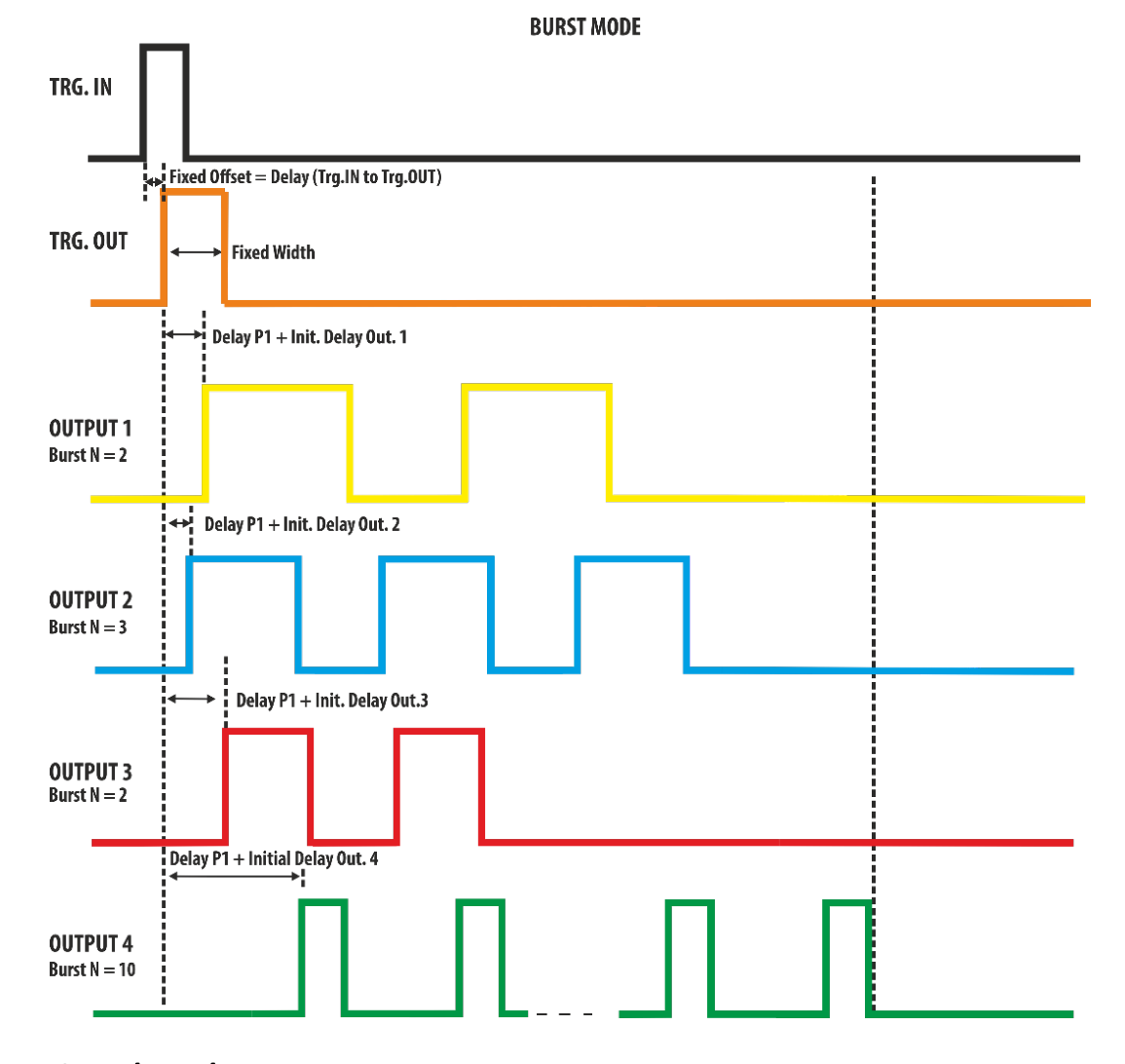
Burst Mode
Burst mode is similar to Single mode, but a programmed number of Output Pulses is generated for each trigger signal that it is detected on the selected output, rather than just once. This number can be programmed from 1 to 4294967295 by selecting the Burst[N] parameter on the user interface. The trigger source can be sent externally using the TRG.IN connector or internally using the front panel button, SCPI command and timer.
The Output pulses will follow the Trigger Output signals by a Delay user parameter plus an Initial channel delay parameter. In this mode the output signals will be repeated by the number of times specified in the Burst parameter. The time between Output pulse is specified by the Period and the duration of each Output pulse is specified by Width. The Trigger Output width is fixed and its duration is about 10 ns.
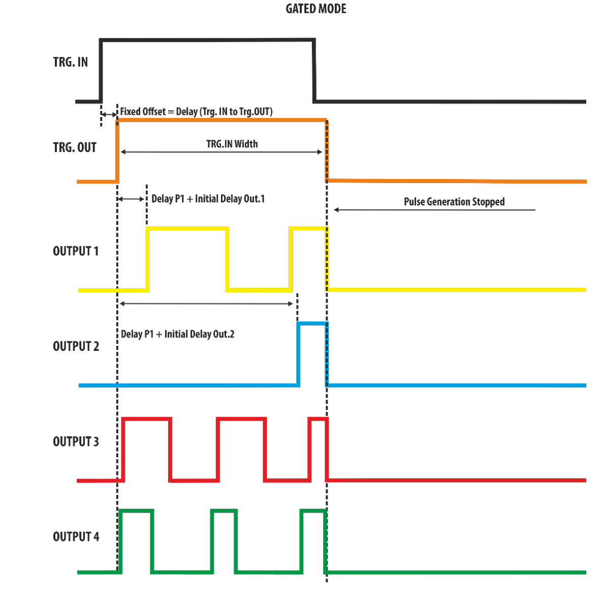
Gated Mode
In Gated mode the Output Pulses of the programmed Width occur at the rate specified by Period as long as the Trigger signal is true. The trigger source can be sent externally using the TRG.IN connector or internally using the front panel button, SCPI command and timer. The Trigger signals starts the Model 765 timebase and one TRG.OUT signal follows each trigger by a Fixed Offset equal to the Trigger IN to Trigger OUT Delay. The width of the Trigger Output will be equal to the width of the Trigger IN signal.
- If the Output channel linked to the Trigger Output Source is disabled (OFF state), the TRG.OUT signal will not follow that output. Its state will be 0 or 1 depending on the selected polarity.
- If all channels will be disabled, the TRG.OUT signal state will be 0 or 1 depending on the selected polarity.
In Gated mode the Output pulses start after the Delay parameter plus a fixed offset below 100 ns and continue to run at the rate defined by Period, for the duration of the true state of the Trigger signal. If the Trigger Output signal goes false while an Output pulse is active, the generation of the output pulses will be stopped.
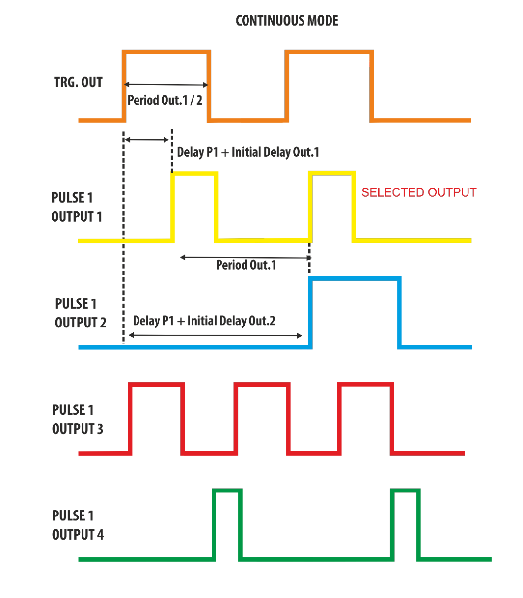
Continuous Mode
Continuous mode produces a continuous pulse stream at the selected Period and Width. One Trigger Output pulse will occur for each Pulse 1 relative to the selected Output channel in the Trigger Source dropdown list.
The width of the Trigger Output will be equal to the Period of the selected output divided by 2: Trigger Output Width = Period / 2 of the selected output. The Output Pulse follows the Trigger Output by a Delay parameter.

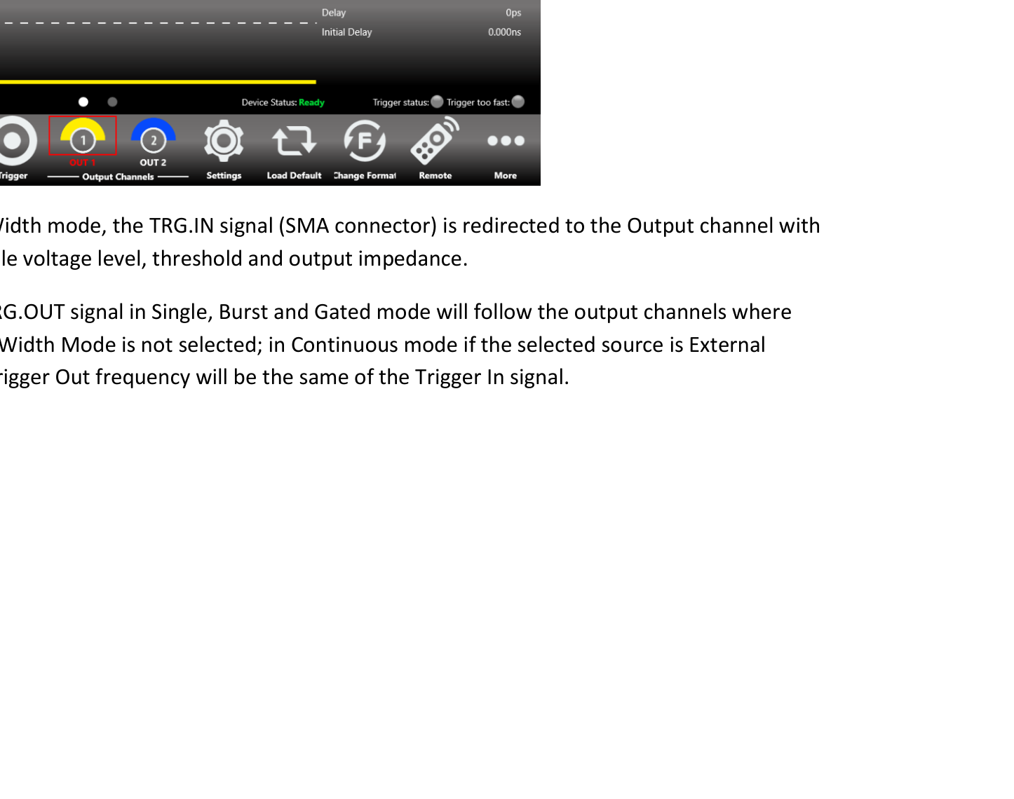
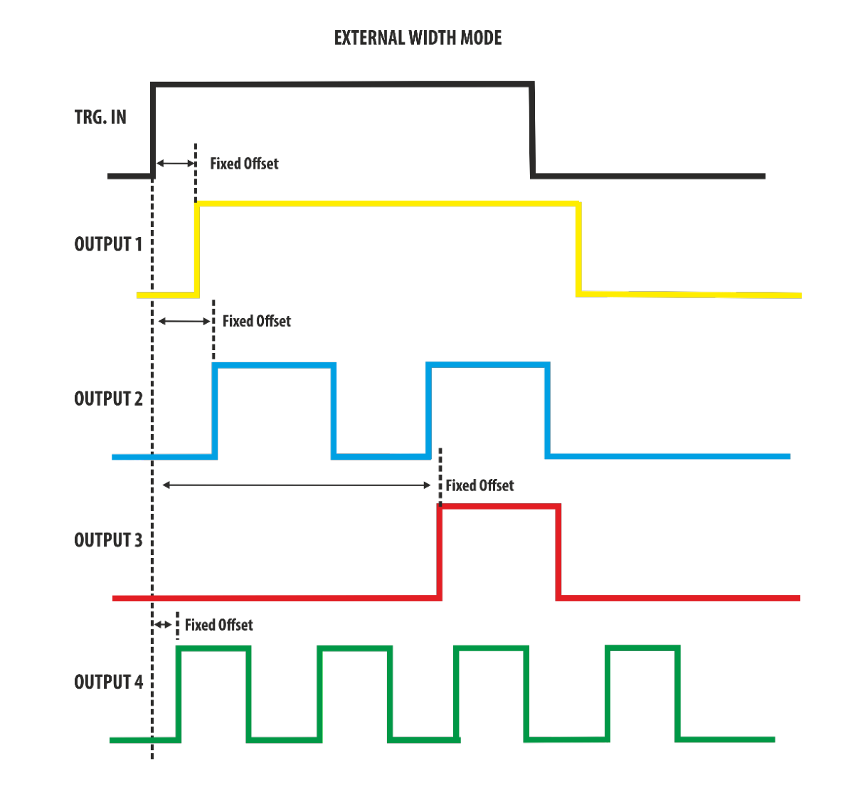
External Width Mode
In External Width mode, the TRG.IN signal (SMA connector) is redirected to the Output channel with programmable voltage level, threshold and output impedance.
Multiple Pulse Interactions
Here below is described the interaction of multiple pulses with the various Trigger Modes:
- Continuous Mode. Depending on the multiple pulse selection, two, three or four Pulses follow each Trigger Output rather than one.
- Single Mode. Same as Continuous mode for the exception that the group of pulses are generated only once.
- Burst Mode. In this case the Burst N parameter specifies the number of Output Pulse groups (two, three or four) per trigger, rather than the number of Output Pulses. As an example, in case of Double Pulse, the first pulse of the first pair in any burst will follow the leading edge of the Trigger Output by Delay 1 + Initial Delay Out.1, the second pulse in any pair follows the first by the Delay parameter, and the first pulse of any pair follows the first pulse of the previous pair by the Period parameter.
- Gated Mode. Same as Continuous mode for the exception that the group of pulses are generated when the Trigger signal is in true state.
- External Width Mode. Its function is the same of single pulse, it is unaffected by the state of Multiple Pulses.
9. Quick Start
Single Pulse
If you are a beginner user, follow these steps to generate your first pulse signal.
- Power on. Connect the power cord and push the front-panel on/off switch to turn on the instrument.
- Connect the output. Connect Output 1 of the instrument to the oscilloscope input with a cable, and select 50 Ohm load on the oscilloscope input.
- Open Settings. Touch the Settings button on the SimpleRider UI.
- Select Continuous. In Settings → Trigger Setup, select Continuous as Trigger Mode.
- Enable an output. By default OUT1 and OUT2 are OFF (the output is disconnected from the load using a relay). Press the OUT1 button to enable it; press OUT2 to select OUTPUT2, press it again to enable it.
- Start. Press the Start button.
- Observe. Observe the pulse waveform displayed on the oscilloscope screen.
- Close Settings. Press the Settings button again to close the Settings page.
- Set levels. Touch Voltage High [V] to set the output pulse high level. You can also select Period, Delay or Width using the touch screen or the front-panel physical buttons.
- Adjust. Change the output pulse parameters using the virtual or physical numeric keypad, the general-purpose knob and arrow keys, or keyboard and mouse.
Double Pulse
- Power on. Connect the power cord and push the front-panel on/off switch to turn on the instrument.
- Connect the output. Connect Output 1 to the oscilloscope input and select 50 Ohm load.
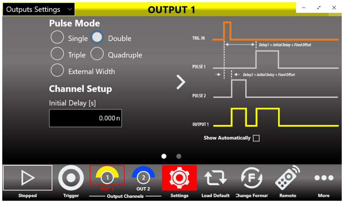
- Select Double Pulse. Press the Settings button, select "Outputs Settings" in the dropdown menu and select the Double Pulse option in the Pulse Mode for Output 1.
- Set the trigger. Select "Trigger Settings" to open the Trigger Setup page and select Single as Trigger Mode and Button Only as Trigger Source.
- Start. Press the Start button.
- Trigger and observe. Set a Single acquisition on the oscilloscope, set the scope trigger and press the Trigger button. Each time you press Trigger you observe a group of two pulses on the scope.
- Close Settings. Press the Settings button again to close the Settings page.
- Adjust Pulse 1 delay. Touch the Output 1 → Pulse 1 Delay parameter to change the Pulse 1 delay. You can also select Amplitude, Period or Width.
- Swipe to switch pulses. Use the swipe gesture at the top of the display to change the Pulse selection from Pulse 1 to Pulse 2 and back.
- Adjust. Change the output and pulse parameters using the keypads, knob and arrows, or keyboard and mouse.
10. SimpleRider PG Software
User Interface Description
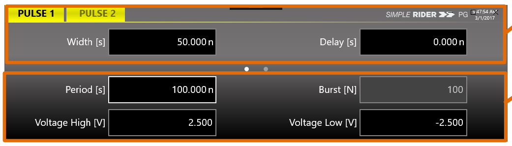
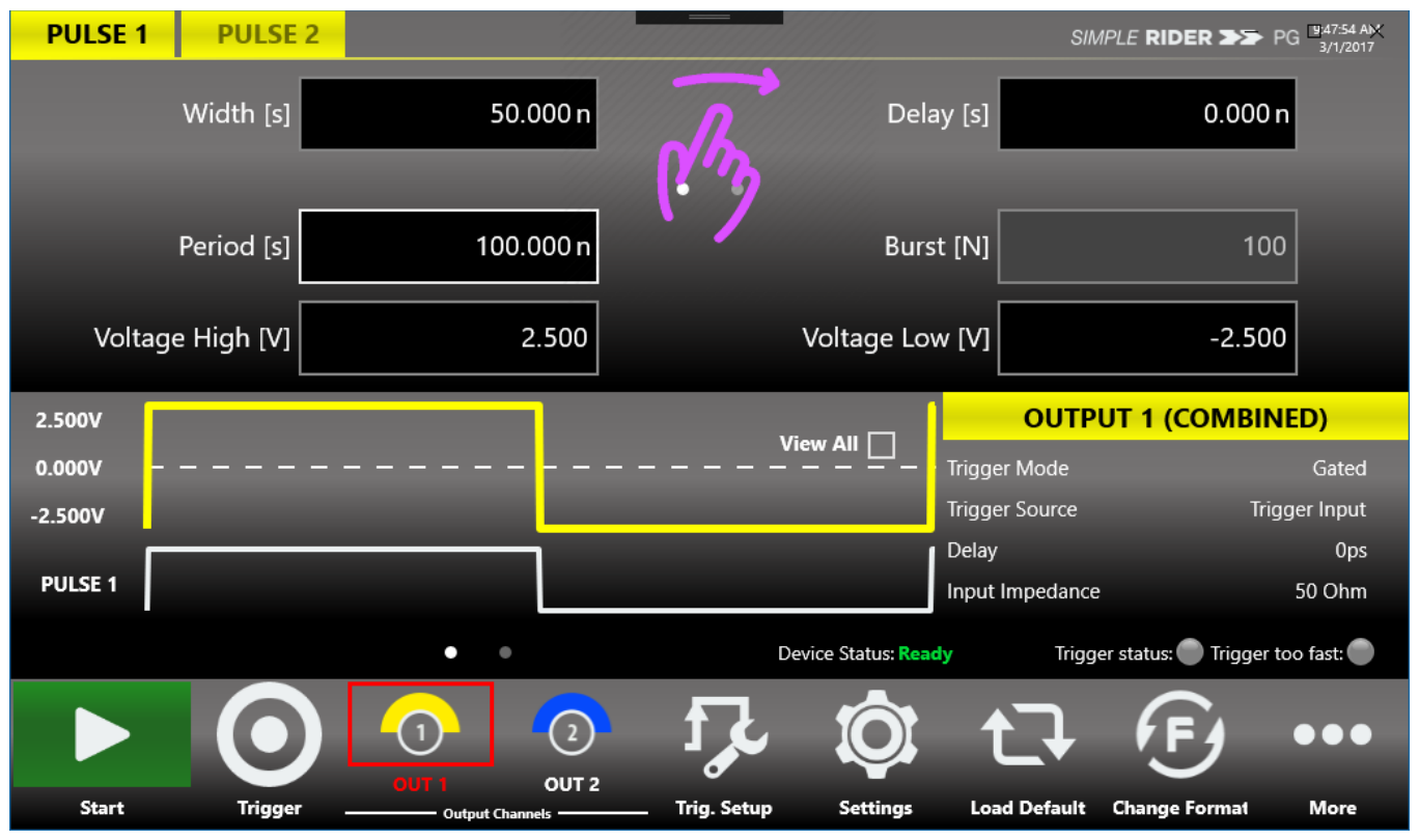
The SimpleRider software environment provides easy access to all product functions and parameters. It consists of three main elements: the Pulse and Output channel parameters area, the Waveform Graph area, and the command bar. The display is a 7" capacitive touch screen; you can access parameters and generate pulses quickly with a few screen touches.
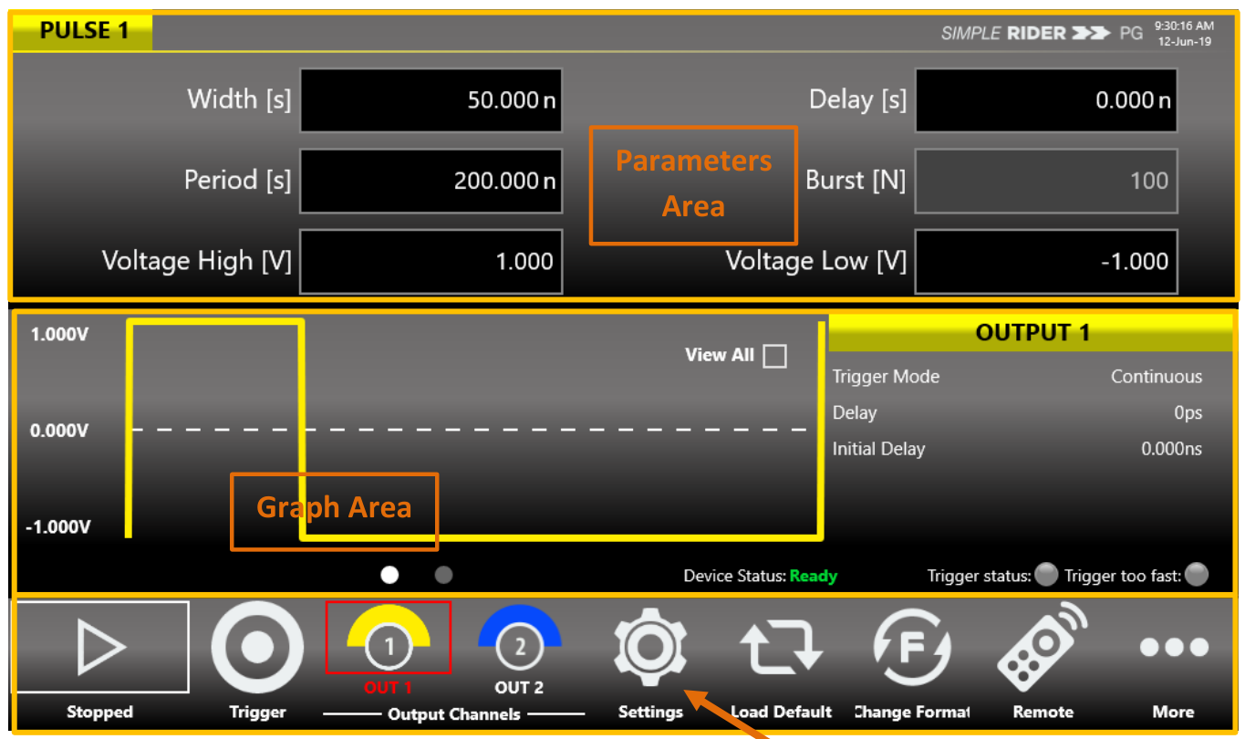
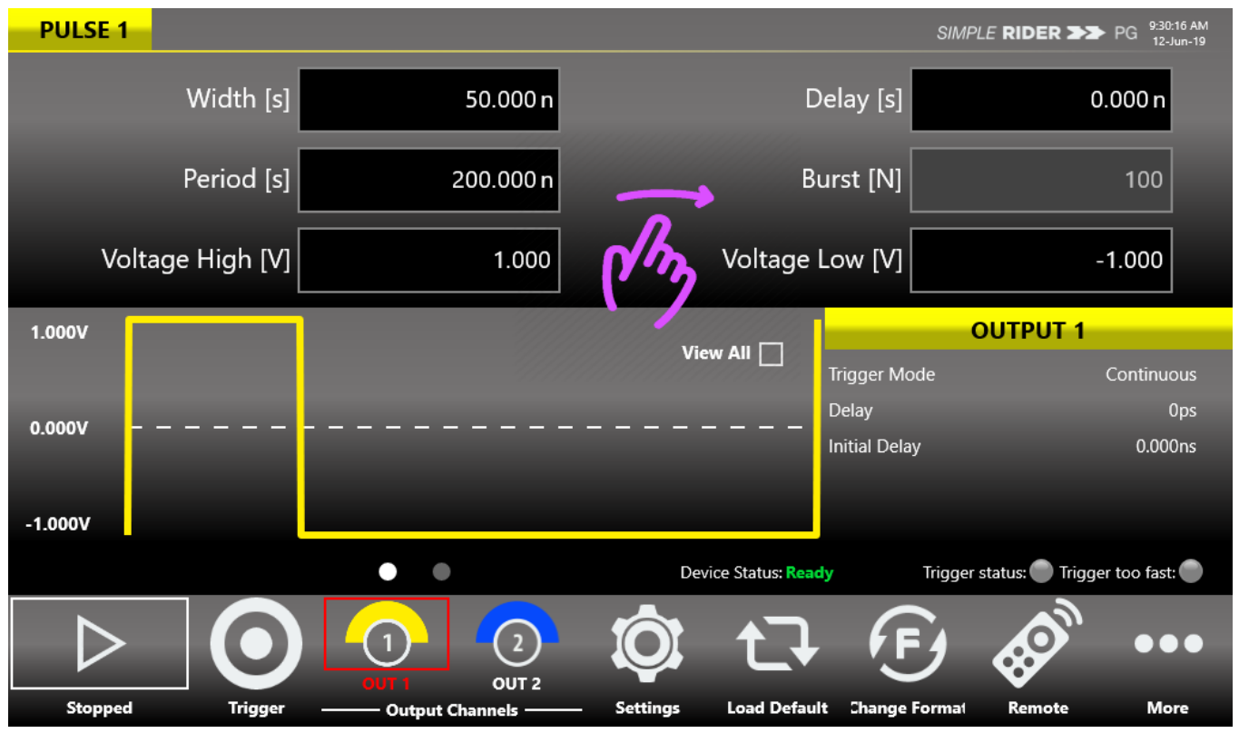
Parameters Area
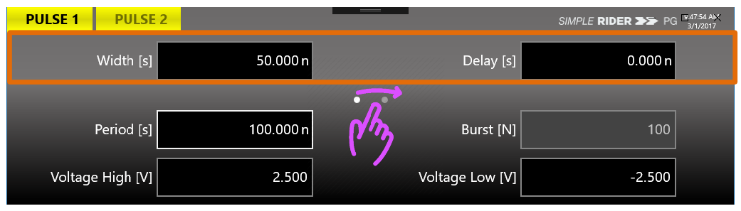
If the Multiple Pulses feature is off, use a swipe left or right gesture to change the output channel selection. If the Multiple Pulses feature is on, swipe left or right on the upper part of the screen to change the Pulse selection, and on the lower part to change the Output selection. With Multiple Pulses off, the parameters area gives access to Pulse 1 (Width, Delay) and to the selected output parameters (Period, Voltage High, Voltage Low and Burst number).
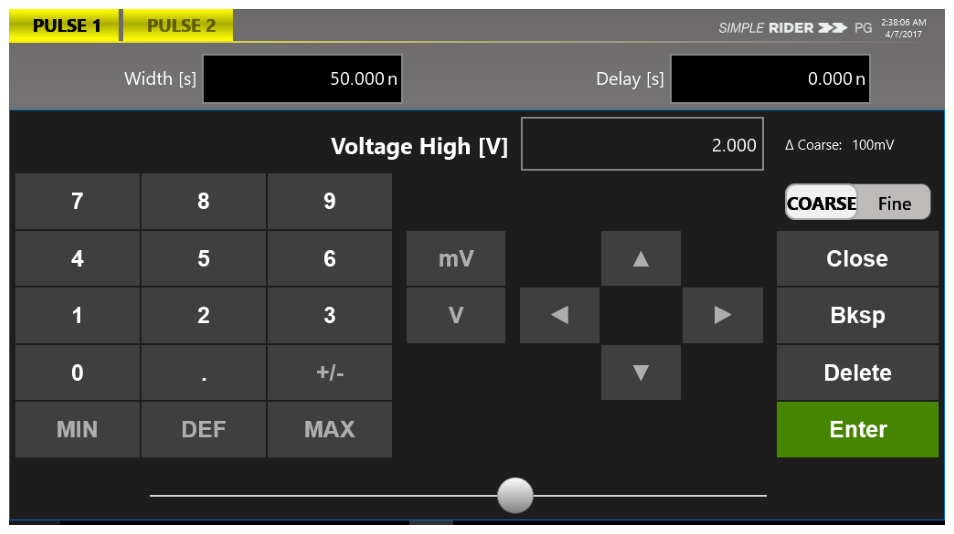
Touch the parameters area to open the virtual numeric keypad, then edit the parameter value and its measure unit. The keypad area displays the parameter name, value and unit; select the digit to modify by touching it or using the left/right arrows, and the selected digit highlights in blue. Each number pressed is shown on the display.
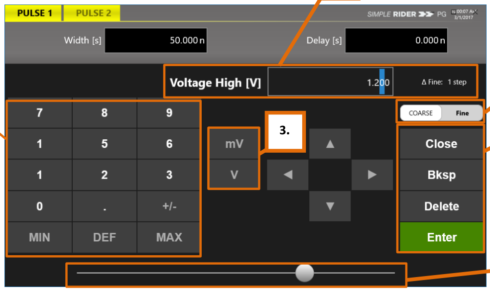
Touch MIN. and MAX. to display the minimum and maximum allowed value for the selected parameter; touch DEF. to set the default value. Coarse / Fine changes the granularity of the increment: in Fine, the increment is 1 for the selected digit; in Coarse, the Delta increment is displayed and the value changes in steps of the selected increment. The Close button closes the keypad without applying changes; Enter confirms and applies them; Bksp deletes a key press and Delete clears the entry. A horizontal scrollbar lets you change the selected value quickly; rotary-knob and scrollbar increments are applied on the fly.
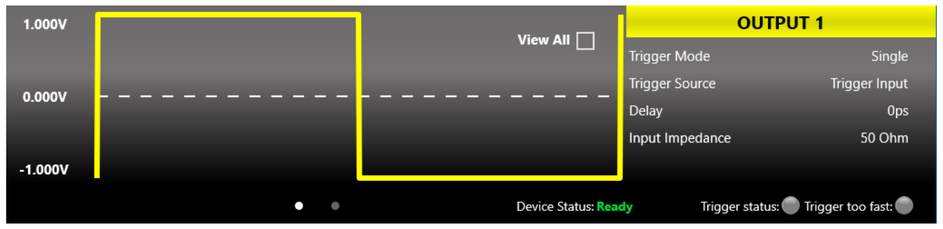
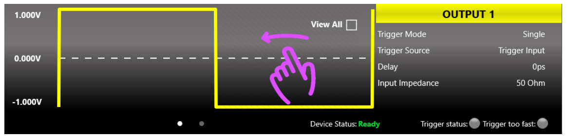
Graph Area
The graph area displays the output channel and/or pulse waveforms with a vertical legend containing the voltage high, low level and offset. The right side displays the channel name and the main current settings (Trigger Mode, Source, Amplitude, Trigger Input Impedance and so on). The bottom shows the Device Status, Trigger Status and Trigger Too Fast indicators. Device Status "Ready" means the instrument is stopped and ready to start; pressing Run changes it to "Running" (ready to receive a trigger). The Trigger Status LED notifies you when the trigger signal is received. The Trigger Too Fast LED notifies you that a trigger event was latched but the trigger frequency is too high to rearm before completing the previous event, so some trigger events may be lost. If Double, Triple or Quadruple output pulse mode is selected, the upper area shows the output signal graph and the lower area shows the selected pulse graph.
Command Bar Area
The command bar contains several touch buttons to control the instrument.
| Button | Description |
|---|---|
| START/STOP | Sets the instrument to Running or Ready (Stopped). In Continuous mode, pressing Start begins output pulse generation and pressing it again stops it. In Single, Gated and Burst mode the button arms the instrument to receive the trigger, and output pulses are generated as soon as the trigger is received. |
| Trigger Button | Sends an internal software trigger to the instrument. |
| Output Channels Buttons | OUT1 to OUT4 change the output channel page; pressing again turns the output OFF or ON via a relay (PG-1074 has four, PG-1072 has two). |
| Settings Button | Opens the Settings page, giving access to the Trigger, Output and Clock settings. |
| Load Default | Loads the default settings. |
| Change Format | Changes the format of the output and pulse parameters. Format A: Period, Width, Delay, Phase, Voltage Level High, Voltage Level Low. Format B: Frequency, Duty Cycle, Phase, Amplitude, Offset. |
| Remote Button | Enters or exits Remote Mode. |
| More Button | Accesses other features and the More menu. |
The More menu includes: Exit (closes the application), Exit Full Screen (exits full-screen mode so you can access Windows OS), Calibration (Self Calibration and Diagnostic), Default (loads the default settings), Load From (loads a saved configuration), Save As (saves the current configuration), Export (exports the current configuration), Numeric Keyboard (enables or disables the virtual keyboard), Beep (enables or disables the beep audio signal on touch), About (firmware release number and instrument serial number) and Help (opens the User Manual).
11. Configurations
A configuration contains the data in proprietary format relative to the current instrument settings. You can save and load the instrument settings using the "Save As.." and "Load From..." buttons.
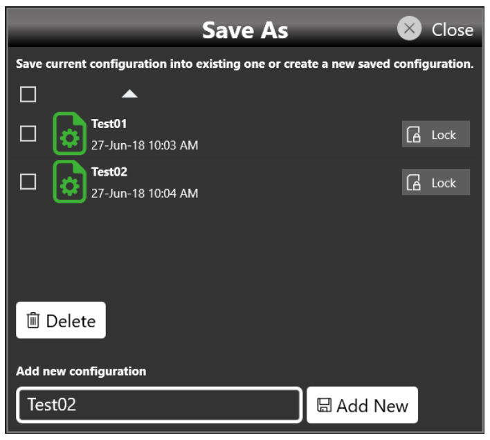
Save As...
A configuration can be saved with the "Save As" button, which opens a dialog box. The configuration is saved in the configuration list that can be accessed by the "Load From" dialog box. In this page you can add a new configuration entry or overwrite an existing one. To create a new entry, write a name in the text box at the bottom of the page and click "Add New".
Export Configuration
If you touch the Export Configuration button, a proprietary binary .zip file relative to the current configuration is exported. The exported file can be used to share configurations between different users or instruments.
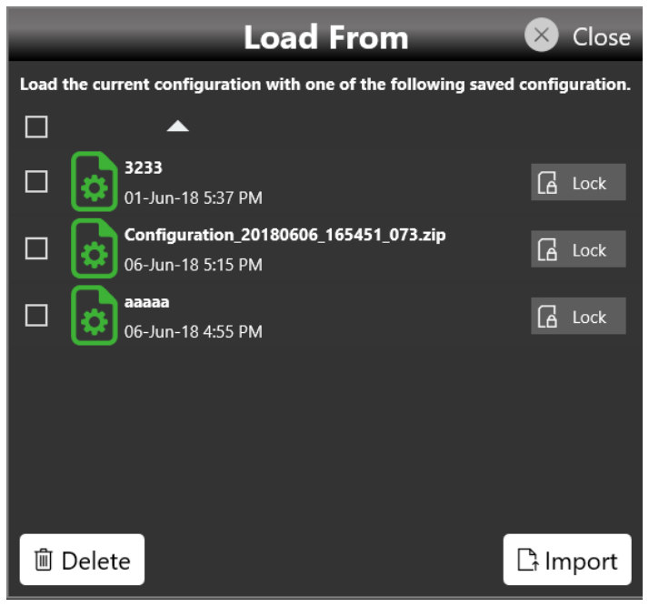
Load From...
Touching the "Load From" button in the "More" menu opens a page that shows the list of all the saved and imported configurations. If you select an existing configuration, you load all its settings into the instrument. In the Load From page you can also manage the configuration list: you can delete, import or lock a configuration. When a configuration is locked it cannot be deleted or overwritten. If you touch the Import Configuration button you can import a configuration file that comes from a different machine or a different user; the imported configuration is inserted in the Load From list.
12. Settings
The Settings button gives access to the Output, Trigger and Clock Settings pages.
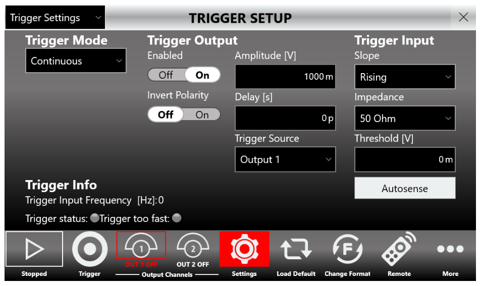
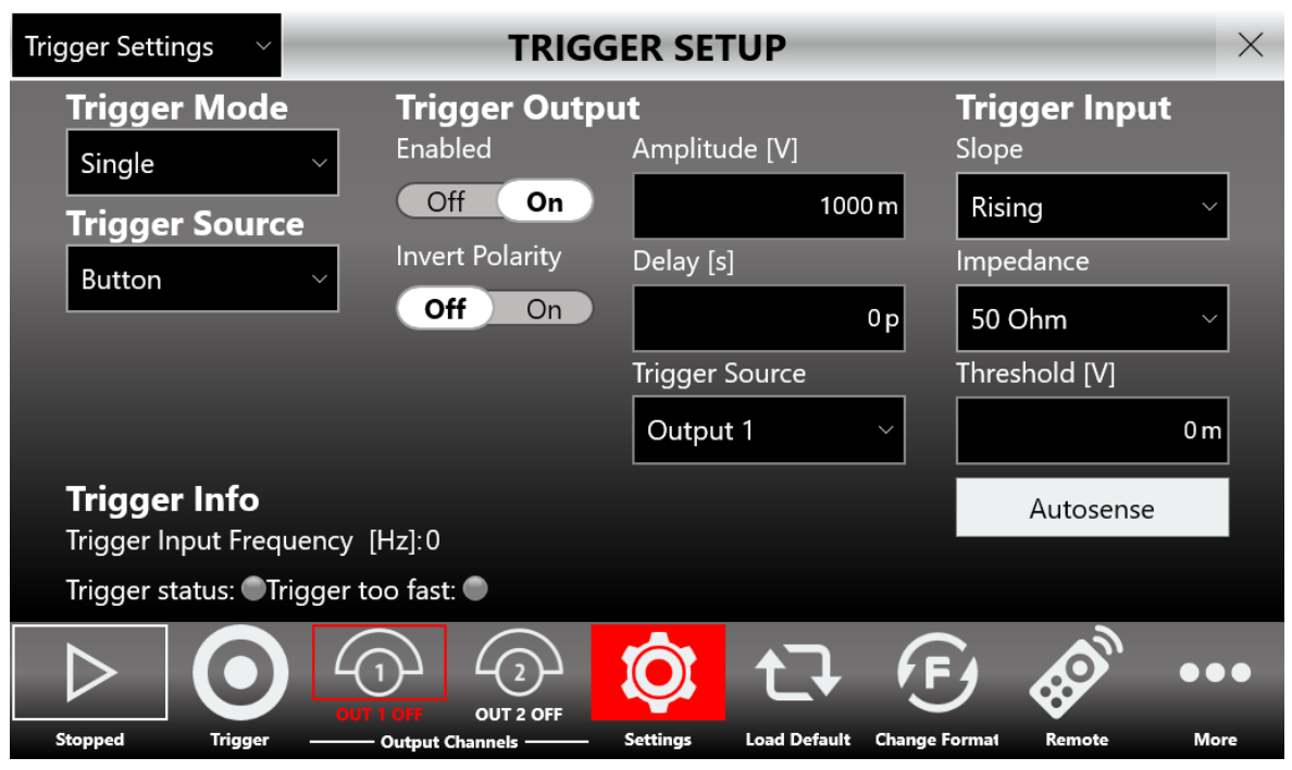
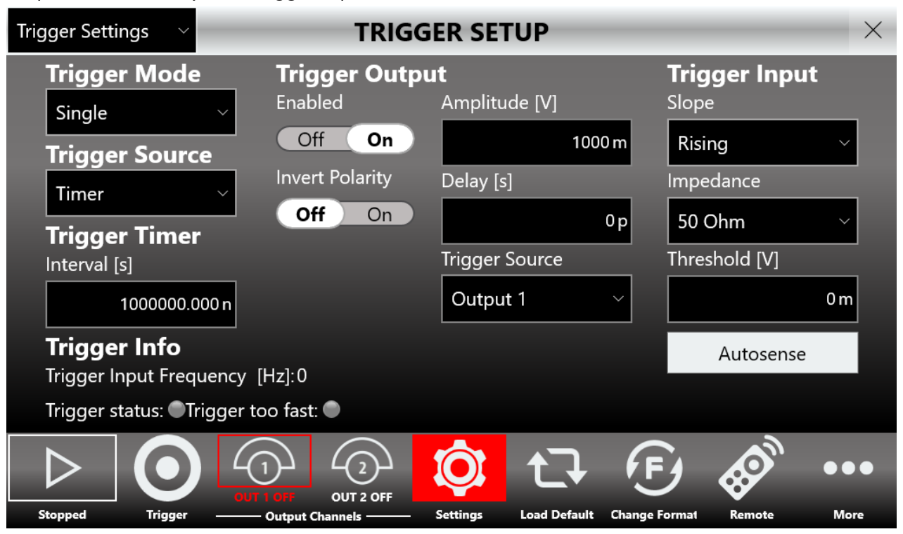
Trigger Setup
Press the Settings button and select "Trigger Settings" on the dropdown list to open the Trigger Setup page, where you can select the Trigger Mode, the Trigger Source, the Trigger Output Amplitude and Delay, the Trigger Input and the Timer characteristics.
| Trigger Control | Description |
|---|---|
| Trigger Mode | The Model 765 has four trigger operating characteristics: Single, Burst, Gated and Continuous. Read the Trigger Controls section for a detailed explanation. |
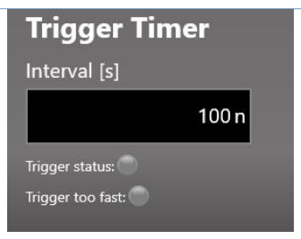
| Trigger Source | External: the instrument receives the trigger from the TRG.IN SMA connector and from the Trigger button. Timer: the trigger is linked to the software internal Timer and the Trigger button; set the timer value from 20 ns to 50 seconds, and when you press Start the countdown begins and a trigger is generated as soon as it reaches zero. Button: the trigger comes from the software (UI button or SCPI commands) or the front-panel button only. |
| Trigger Info | Indicators that display the Trigger Input Frequency and whether the trigger has been missed or is too fast. |
| Trigger Output | In Single, Burst, Continuous and Gated mode, set the Trigger Output Amplitude, the Delay [s] from the Trigger In signal and the Trigger Output Polarity. You can also select the Trigger Output Source from Output 1 to Output 4 on the PG-1074 models and Output 1 to Output 2 on the PG-1072 model. The Trigger Output pulse is then linked to the selected output. |
| Trigger Input | In Single, Burst and Gated mode, set the Trigger Input Threshold, the slope (positive or negative) and the input impedance (50 Ohm or 1 k Ohm). Pressing Autosense lets the instrument automatically measure the threshold of the signal applied to the Trigger In port. |

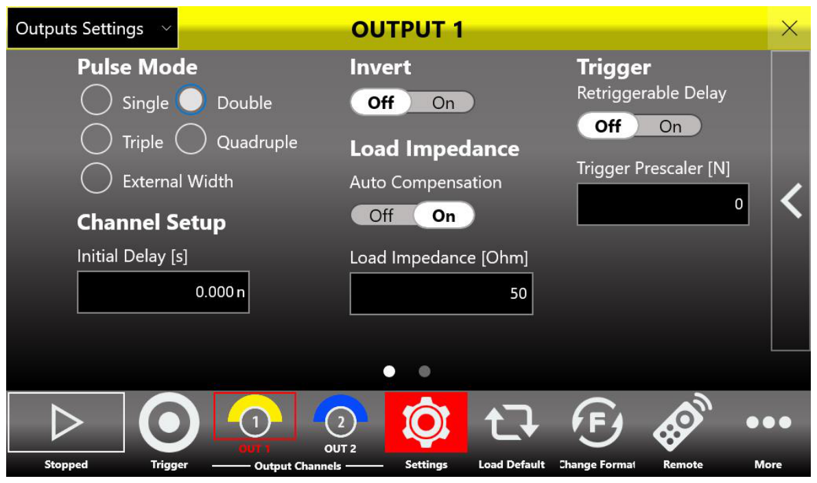
Output Settings
Press the Settings button and select "Outputs Settings" on the dropdown menu to open the page where you set output channel features such as the pulse mode (single, double, triple or quadruple), the load impedance and the output polarity.
| Control | Description |
|---|---|
| Pulse Mode | Selects the pulse mode as single, double, triple or quadruple. To obtain the maximum 800 MHz repetition rate, select Quadruple mode with Period 5 ns and Width 0.625 ns on each pulse, and Delays of 0 ns on Pulse 1, 1.25 ns on Pulse 2, 2.5 ns on Pulse 3 and 3.75 ns on Pulse 4. |
| Invert | When ON, inverts the output polarity. |
| Impedance Value [Ohm] | If Auto Load Compensation is Off, specify the load impedance attached to the selected output connector. |
| Auto Load Compensation | When On, the instrument automatically corrects to deliver the displayed voltage levels to any load from 50 Ohm to 100 M Ohm. |
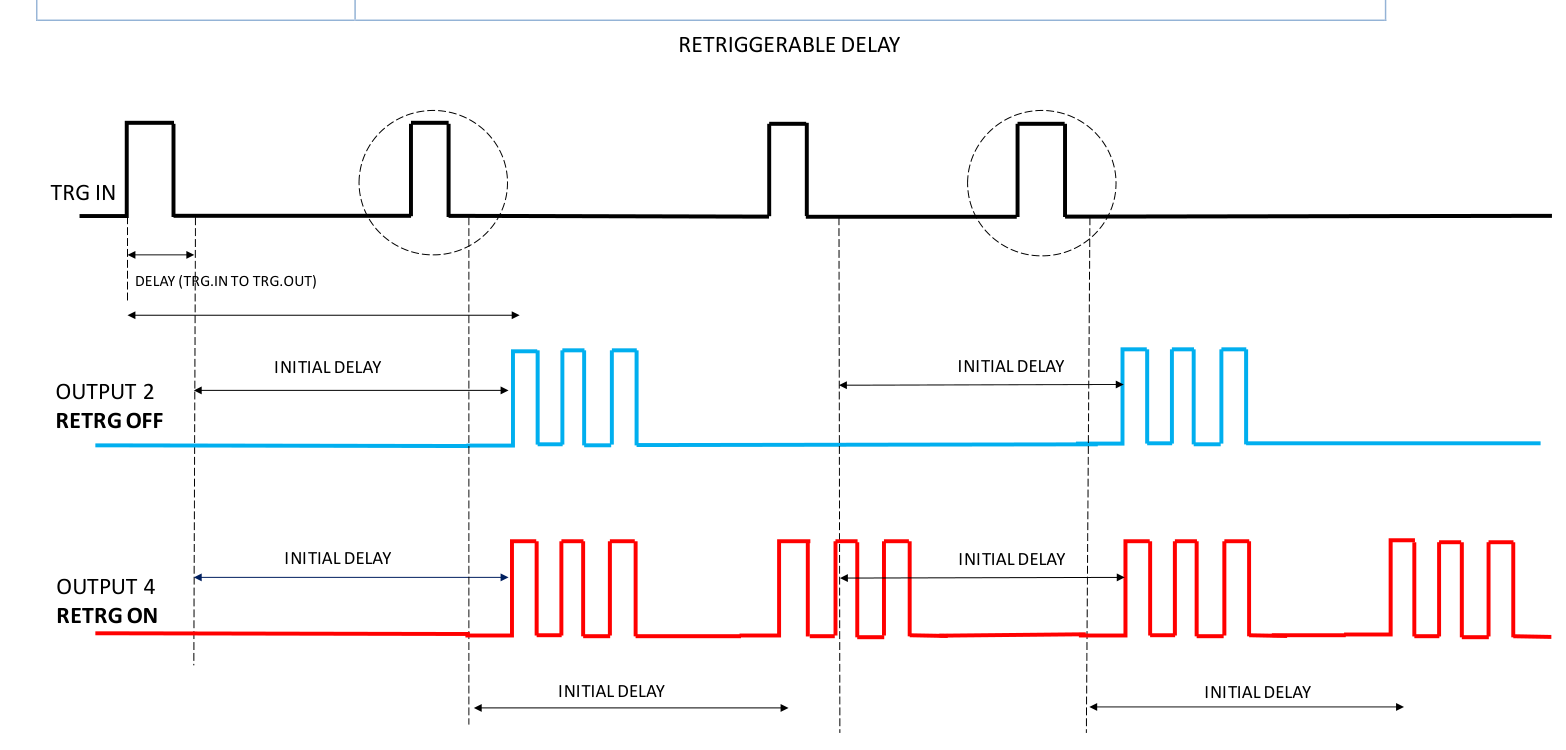
| Initial Delay [s] | The initial delay of the selected channel from the Trigger Output signal. Output pulses follow the Trigger Output by a Delay user parameter plus the Initial Delay. |
| Retriggerable Delay | If Off, on a trigger event the instrument waits for the Initial Delay before starting output pulse generation, ignoring trigger events that arrive during the Initial Delay. If On, the instrument records all trigger events that arrive during the Initial Delay for up to 2.5 us, so trigger events during the Initial Delay can be detected; this allows the maximum trigger rate independently of the Initial Delay you set. |
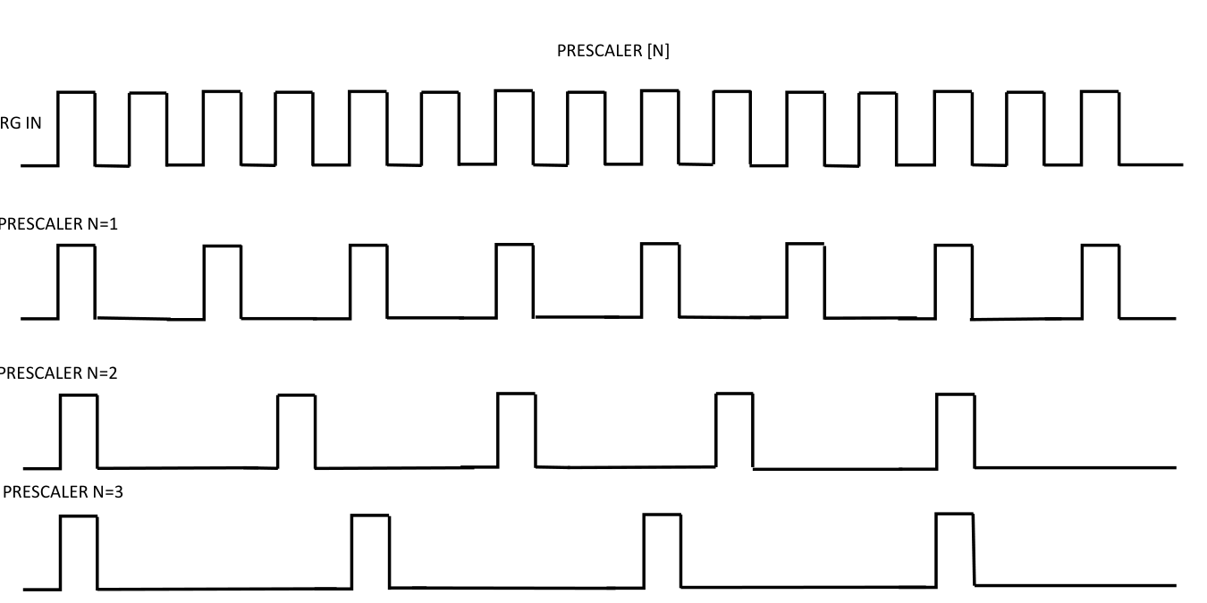
| Trigger Prescaler [N] | The number of Trigger IN edges discarded by the instrument from the last valid edge. It is a value from 0 to 65535, where 0 means no edges are discarded, 1 means one edge is discarded and so on; for example, this lets you decrease the Trigger IN rate. |

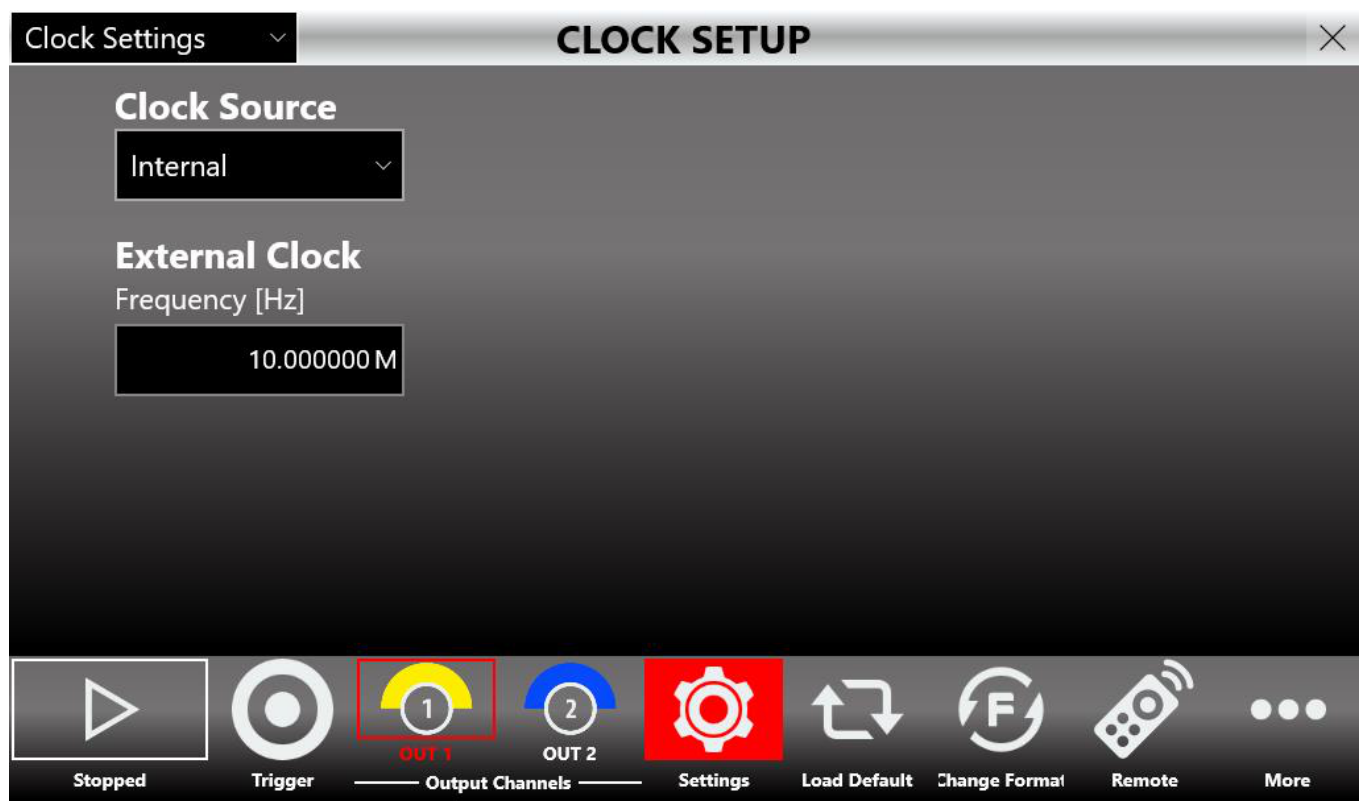
Clock Settings
Press the Settings button and select "Clock Settings" on the dropdown menu to open the Clock Setup page. Clock Source specifies the clock source as Internal or External. With Internal Clock, the instrument time base is synthesized using a reference clock generated internally. With External, the time base is synthesized using the clock provided externally to the Ext. Clock IN SMA connector. External Clock Frequency [Hz]: when External is selected, specify the External Clock Frequency value from 10 MHz to 100 MHz.
13. Remote / Local Mode & Self Calibration
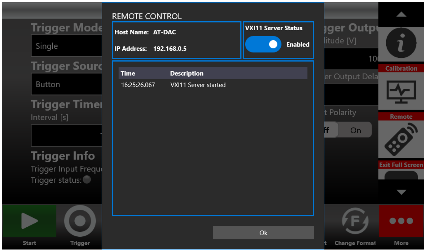
Remote / Local Mode
The Remote/Local page allows you to enable or disable the VXI11 server. By default the VXI11 server is enabled, which means the instrument can accept SCPI commands that arrive from a remote machine; when the instrument receives SCPI commands, the UI changes accordingly. You cannot control the Model 765 instrument by sending SCPI commands on the local machine. If the VXI-11 server is disabled, SCPI command communication is disabled.
Remote Desktop Connection
To connect to the instrument using a remote desktop connection, use the following credentials.
- Computer Name: AT
- User Name: AT
- Password: 1234
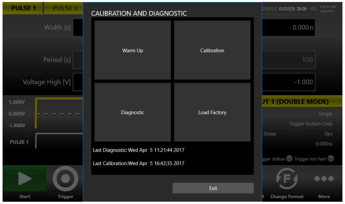
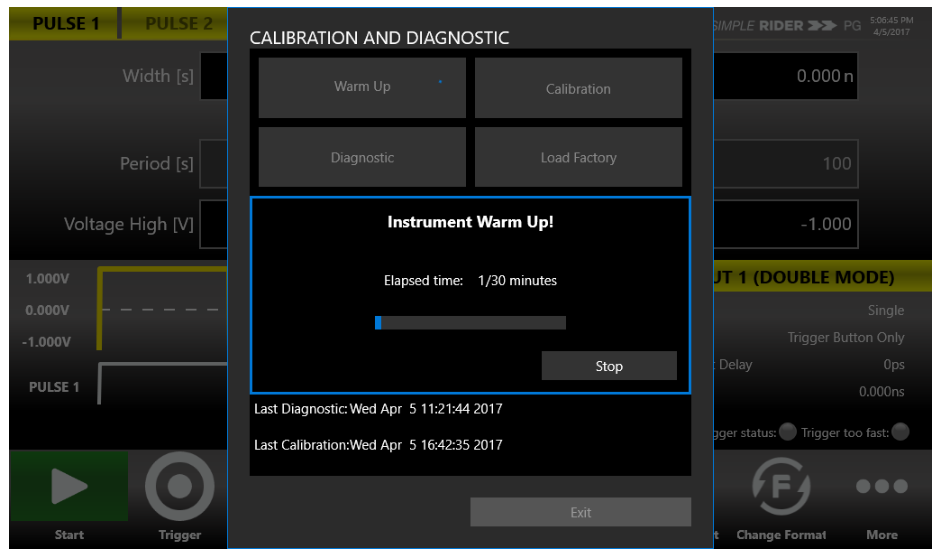
Self Calibration and Diagnostic
The instrument performs a limited set of hardware tests at power-on. You can also perform Self Calibration and Self Diagnostic from the More → Calibration and Diagnostic page.
Self Calibration
This calibration primarily checks DC accuracy using the internal calibration routines.
- Open the page. Click More → Calibration and Diagnostic.
- Warm up. Click the Warm up Timer; a dialog shows the warm-up timer. Wait 30 minutes (press Stop to terminate warming up).
- Stop the timer. When 30 minutes is shown, press Stop.
- Start Self Calibration. Click Self Calibration to start; a dialog appears.
- Wait. Self Calibration may take more than 10 minutes; it can be stopped with Stop.
- Close. When complete, press Close.
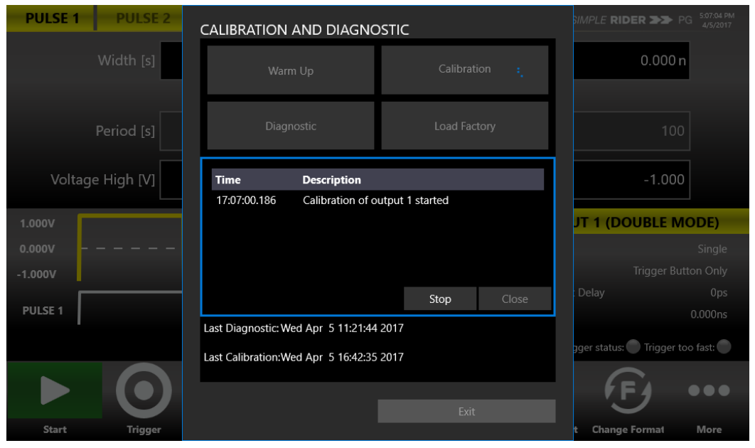
Self Diagnostic
This test verifies that your instrument is operating correctly. Allow a 30 minute warm-up period first.
- Open the page. Click More → Calibration and Diagnostic.
- Warm up. Click the Warm up Timer and wait 30 minutes, then press Stop.
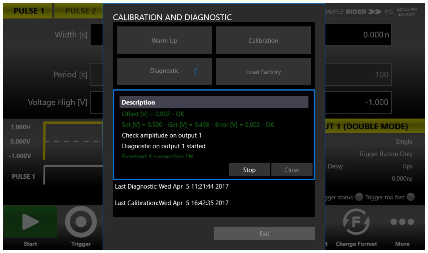
- Start Self Diagnostic. Click Self Diagnostic; a dialog appears and the diagnostic starts.
- Monitor. You can interrupt the self diagnostic by pressing the Stop button. During the operation, the steps are displayed under the Description section.
- Close. When the procedure is displayed as complete, close the window.
Quick Tips
- Warm up first. Allow a 30 minute warm-up period before executing Self Calibration or Self Diagnostic.
- Disconnect cables. Disconnect all the cables from the instrument before you perform Self Calibration or Self Diagnostic.
- Calibrate periodically. It is recommended that the Self Calibration be performed along with a periodic check.
- Do not power off. Do not power off the instrument during Self Calibration or Self Diagnostic. If the power is turned off during Self Calibration, reload the Factory Calibration parameters.
14. Contact
Berkeley Nucleonics Corporation. Phone: (415) 453-9955. Email: info@berkeleynucleonics.com. Address: 2955 Kerner Blvd, San Rafael, CA 94901. Web: www.berkeleynucleonics.com.
Model 765 User Manual. Document Version Number: Rev B, 2.3. Print Code: 02025060.
15. Programming & SCPI Command Reference
The Model 765 can be operated remotely using SCPI (Standard Commands for Programmable Instruments) commands. This reference applies to both Rev. A (500 MHz system) and Rev. B (800 MHz system) of the Model 765 Pulse Generator Series. Commands marked Model 765 Rev. B only are available on the 800 MHz system only.
Remote Interfaces and Prerequisites
The instrument is controlled over a network using the VXI-11 (LAN) protocol, allowing remote control with SCPI commands. Control runs through the standard Windows utilities and the National Instruments VISA (NI-VISA) implementation of the VISA I/O standard, which provides the programming interface between the hardware and development environments such as Visual Studio .NET, LabVIEW, LabWindows/CVI, Measurement Studio and MATLAB.
- Connect your LAN cable to the instrument.
- Install the latest NI-VISA package on the Client-PC, then install the latest version of the NI-VISA tools.
The instrument VXI-11 LAN server provides software connectivity between the instrument and remote PCs over an Ethernet LAN. The AT-Pulse-Rider-SDK contains example programs written in LabVIEW (requires at least LabVIEW 2013 64-bit), Microsoft Visual C++ and Microsoft C# .NET; the programs run on Microsoft Windows PC-compatible systems equipped with NI-VISA and assume the system recognizes the PC (external controller) resource name.
Command Syntax Conventions
Control the operations and functions of the instrument through the LAN interface using commands and queries. The related topics below describe the syntax of these commands and queries. A command consists of set commands and query commands (usually called commands and queries). Commands modify instrument settings or tell the instrument to perform a specific action. Queries cause the instrument to return status or setting information. A command message is a command or query name followed by any information the instrument needs to execute the command or query. The following symbols are used throughout this documentation.
| Symbol | Meaning |
|---|---|
| < > | Defined element |
| ::= | Is defined as |
| | | Exclusive OR |
| { } | Group; one element is required |
| [ ] | Optional; can be omitted |
| . . . | Previous elements can be repeated |
| ( ) | Comment |
A command or query name often has both a long form and a short form. The short form is shown by the upper-case characters, the long form by the full keyword (for example SOURce or SOUR). You can enter commands in upper-case, lower-case, or a combination, and you may insert white space between command keywords. A query is a command followed by a question mark (?).
- Header. The basic command name. If the header ends with a question mark, the command is a query. The header may begin with a colon (
:) character; if omitted, the instrument assumes the command begins at the root node. - Mnemonic. A header subfunction. Some command headers have only one mnemonic; a header with multiple mnemonics is separated by a colon (
:) character. - Argument. A quantity, quality, restriction or limit associated with the header. Some commands have no arguments; others have one or many. A
<Comma>separates arguments from one another. - Comma. A single comma between arguments of a multiple-argument command.
- Space. A white space between a command header and the related argument. A white space may consist of multiple white-space characters.
Use a semicolon (;) to concatenate any combination of set commands and queries (concatenated commands are executed in the order received). Separate completely different headers with a semicolon and the leading colon on all commands except the first one, for example SOURce1:VOLTage 1V; SOURce1:VOLTage:OFFSet 0.5V. This documentation uses <EOM> to represent a message terminator.
Parameter Types and SI Prefixes
| Parameter type | Description | Example |
|---|---|---|
| Boolean | Boolean numbers or values | ON or 1, OFF or 0 |
| NR1 numeric | Integer numbers | 0, 1, 15, -1 |
| NR2 numeric | Decimal numbers | 1.2, 3.141, -6.5 |
| NR3 numeric | Floating point numbers | 3.1415E+9 |
| NRf numeric | Flexible decimal that may be type NR1, NR2 or NR3 | See NR1, NR2 and NR3 examples in this table |
| String | Alphanumeric characters (must be within quotation marks) | "Testing 1, 2, 3" |
If the decimal numeric argument refers to voltage, frequency, impedance or time, express it using SI units; instead of using the scaled explicit point input value format <NR3> (SI units are units that conform to the System International of Units standard), for example use the input format 200 mV or 1.0 MHz instead of 200.0E-3 or 1.0E+6 respectively, to specify voltage or frequency. The SI prefixes that must be included are shown in the table below; you can enter them in upper-case or lower-case characters.
| SI prefix | Corresponding power |
|---|---|
| EX | 1018 |
| PE | 1015 |
| T | 1012 |
| G | 109 |
| MA | 106 |
| K | 103 |
| M | 10-3 |
| U | 10-6 |
| N | 10-9 |
| P | 10-12 |
| F | 10-15 |
| A | 10-18 |
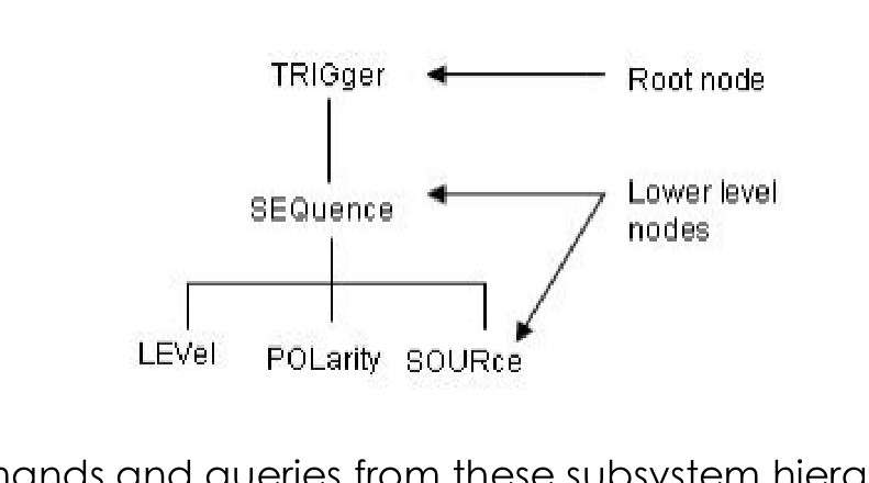
SCPI Command Hierarchy
The pulse generator uses a command language based on the SCPI standard. The SCPI language is based on a hierarchical tree structure that represents a subsystem. The top level of the tree is the root node; it is followed by one or more lower-level nodes. You can create commands and queries from these subsystem hierarchy trees. Commands specify actions for the instrument to perform; queries return measurement data and information about parameter settings.
Status Registers
The instrument maintains several status registers. The Standard Event Status Register (SESR) records events; the Status Byte Register (SBR) summarizes the instrument status. The DESER, ESER and SRER enable registers select which events are reported to the status registers and the Status Byte.
Standard Event Status Register (SESR)
| Bit | Name | Description |
|---|---|---|
| 7 (MSB) | PON Power On | Shows that the instrument was powered on. On completion, the diagnostic tests also set this bit. |
| 6 | URQ User Request | Indicates that an application event has occurred. |
| 5 | CME Command Error | Shows that an error occurred while the instrument was parsing a command or query. |
| 4 | EXE Execution Error | Shows that an error occurred while executing a command or query. |
| 3 | DDE Device Error | Shows that a device error occurred. |
| 2 | QYE Query Error | Either an attempt was made to read the Output Queue when no data was present or pending, or data in the Output Queue was lost. |
| 1 | RQC Request Control | This is not used. |
| 0 (LSB) | OPC Operation Complete | This bit is set when all pending operations complete following an *OPC command. |
Status Byte Register (SBR)
| Bit | Name | Description |
|---|---|---|
| 7 (MSB) | — | Not used |
| 6 | RQS Request Service | Obtained from a serial poll. Shows that the instrument requests service from the GPIB controller. |
| 6 | MSS Master Status Summary | Obtained from the *STB? query. Summarizes the ESB and MAV bits in the SBR. |
| 5 | ESB Event Status Bit | Shows that status is enabled and present in the SESR. |
| 4 | MAV Message Available | Shows that output is available in the Output Queue. |
| 3 | — | Not used |
| 2 | — | Not used |
| 1 | — | Not used |
| 0 (LSB) | — | Not used |
Each Enable Register (DESER, ESER, SRER) acts as a filter to a Status Register: the DESER filters the Event Queue and can prevent information from being recorded in the register or queue. The Device Event Status Enable Register (DESER) controls which types of events are reported to the SESR. Use the DESE command to enable and disable the bits in the DESER. The Event Status Enable Register (ESER) controls which types of events are summarized by the Event Status Bit (ESB) in the SBR; use the *ESE command to set the bits in the ESER, and the *ESE? query to read it. The Service Request Enable Register (SRER) controls which bits in the SBR generate a Service Request; use the *SRE command to set the register and the *SRE? query to read it.
Transferring Data Files (Block Data Format)
On Model 765 Rev. B, when transferring a data file it is convenient to send data in chunks. This allows better memory management, enables you to stop the transfer before it completes, and helps the external controller report progress. Block data is a transmission format suitable for large amounts of data. A command using a block-data parameter with definite length has the structure HEADer:HEADer #45168xxxxxxxx: the hash symbol # introduces the data block, the next number indicates how many of the following digits describe the block length, and those digits give the length in bytes. In this example, the 4 following digits indicate a length of 5168 bytes. During transmission of the data bytes, all End or other control signs are ignored until all bytes are transmitted.
Calibration and Diagnostic Commands
| Keyword | Parameter Range | Notes |
|---|---|---|
*CAL? | <NR1> | Perform self-calibration and return result status. Returns 0 (Pass) or a calibration error code. Allow a 30 minute warm-up before executing; the instrument must reach a valid temperature. |
DIAGnostic | <NR1> | Perform a self-test and return result status. <NR1> = 0 indicates the self-test completed without errors. |
*TST? | <NR1> | Perform a self-test and return result status. <NR1> = 0 indicates the self-test completed without errors. |
Date and Time Commands
| Keyword | Parameter Range | Notes |
|---|---|---|
DATE | <yyyy>,<mm>,<dd> | Set or query the system date. Month 1 to 12, day 1 to 31. Example: DATE 2012,11,20. |
TIME | <hour>,<minute>,<second> | Set or query the system time. Hour 0 to 23, minute 0 to 59, second 0 to 59. |
Memory Commands
| Keyword | Parameter Range | Notes |
|---|---|---|
MEMory:RECall | <file name> | Recall a specified project file in the file system. Model 765 Rev. B only. |
MEMory:SAVE | <file name> | Save the current project file in the file system. Model 765 Rev. B only. |
MEMory:STATe:DELete | <cfg_name> | Delete the setup memory (a configuration). Model 765 Rev. B only. |
MEMory:STATe:LOCK | <cfg_name> | Lock or unlock the setup memory and query whether the memory is locked. |
*RCL | {0|1|2|3|4} | Recall instrument settings from setup memory. Restores the state from a copy of the settings stored in the setup memory. |
*SAV | {0|1|2|3|4} | Save instrument settings to setup memory. Stores the current settings in the specified memory location. |
DELete:SETup | <cfg_name> | Delete a configuration. Model 765 Rev. B only. |
RECALL:SETup | <cfg_name> | Restore the instrument settings from a configuration name; equivalent to PULSEGENControl:SREStore. Model 765 Rev. B only. |
MEMory:NSTates? | <NR1> | Return the number of available configurations saved in the PG. Model 765 Rev. B only. |
MEMory:STATe:CATalog? | <cfg_name>,<cfg_name>,... | List the names of available configurations saved in the PG. Model 765 Rev. B only. |
MEMory:STATe:NAME | <NR1>,<dst_cfg_name> | Copy a configuration <src_name> into a <dst_name> configuration. Model 765 Rev. B only. |
HCOPy (Screenshot) Command
| Keyword | Parameter Range | Notes |
|---|---|---|
HCOPy:SDUMp[:IMMediate] | <file_path> | Copy the current screen-shot image and save it to a specified file. Valid extensions: ".bmp", ".jpg", ".jpeg", ".gif", ".png", ".tiff". The path must be a valid path with the file name and extension. |
Output Commands
| Keyword | Parameter Range | Notes |
|---|---|---|
OUTPut[1|2|3|4][:STATe] | {ON|OFF|0|1} | Set or query the output state (on or off) on a selected output N. ON (or 1) enables the pulse generator output; OFF (or 0) disables it. |
OUTPut[1|2|3|4]:PULSe:MODE | {SINGle|DOUBle|TRIPle|QUADruple|EXTernalWIDTh} | Set or query the pulse mode relative to the output N. SINGle = single pulse, DOUBle = double pulse, TRIPle = triple pulse, QUADruple = quadruple pulse. EXTernalWIDTh available for the selected output if EXTernalWIDTh is selected. |
Display Commands
| Keyword | Parameter Range | Notes |
|---|---|---|
DISPlay:CHANnel | {OUT1|OUT2|OUT3|OUT4} | Select the user interface output channel page. |
DISPlay:UNIT:VOLT | {AMPLitudeoff|HIGHlow} | Select the method for specifying voltage ranges: as an amplitude and an offset, or as a high and low value. |
DISPlay[:WINDow]:TEXT:CLEar | — | Clear the text message from the display screen. Model 765 Rev. B only. |
DISPlay[:WINDow]:TEXT[:DATA] | <message> | Display a text message on the instrument screen. The query form returns the text string currently displayed. Model 765 Rev. B only. |
Source Commands
The source commands set or query the output pulse parameters. SOURce[1|2|3|4] selects the output channel N; :PULSe[1|2|3|4] selects the pulse M relative to that output.
| Keyword | Parameter Range | Notes |
|---|---|---|
SOURce[1|2|3|4]:PERiod | <period> <units>::=[ns|µs|ms|s] | Set or query the period for the output channel. Example: SOURce1:PERiod 200ns. |
SOURce[1|2|3|4]:FREQuency | <frequency> <units>::=[Hz|kHz|MHz] | Set or query the frequency for the output channel. |
SOURce[1|2|3|4]:BURSt:NCYCles | <cycles> (1 to 4,294,967,295) | Set or query the number of cycles (burst count) to output in burst mode for the specified output channel. |
SOURce[1|2|3|4]:INITDELay | <delay> <units>::=[ns|µs|ms|s] | Set or query the initial delay (group delay) from the Trigger IN to the output N when all pulses are associated to the output N. Range 100ns + 10ns + 110ns; the output pulse 2 is delayed by 100ns + 20ns + 120ns. |
SOURce[1|2|3|4]:LOAD:IMPedance | <impedance> (Ohm) | Set or query the load impedance value for the selected output channel. |
SOURce[1|2|3|4]:LOAD:COMPensation | {ON|OFF|0|1} | Enable the automatic calculation of the load impedance for the selected output channel. When ON, the value set through the LOAD:IMPedance command is ignored. Send only when the instrument is stopped. |
SOURce[1|2|3|4]:INVert | {ON|OFF|0|1} | Invert the output polarity. ON (1) inverts the output of channel N; OFF (0) leaves it not inverted. |
SOURce[1|2|3|4]:VOLTage[:LEVel][:IMMediate][:AMPLitude] | <amplitude> <units>::=[V|mV] | Set or query the voltage level amplitude for the specified output channel. |
SOURce[1|2|3|4]:VOLTage[:LEVel][:IMMediate]:OFFSet | <offset> <units>::=[V|mV] | Set or query the offset voltage for the specified output channel. |
SOURce[1|2|3|4]:VOLTage[:LEVel][:IMMediate]:HIGH | <high> <units>::=[V|mV] | Set or query the high level of the output amplitude for the specified channel. |
SOURce[1|2|3|4]:VOLTage[:LEVel][:IMMediate]:LOW | <low> <units>::=[V|mV] | Set or query the low level of the output amplitude for the specified channel. |
SOURce[1|2|3|4]:PULSe[1|2|3|4]:WIDTh | <seconds> <units>::=[ns|µs|ms|s] | Set or query the pulse width for the specified pulse relative to the selected output channel. Pulse Width = Period × Duty Cycle / 100; the pulse width must be less than the period. |
SOURce[1|2|3|4]:PULSe[1|2|3|4]:DELay | <delay> <units>::=[ns|µs|ms|s] | Set or query the pulse delay for the specified pulse relative to the selected output channel. |
SOURce[1|2|3|4]:PULSe[1|2|3|4]:DCYCle | <percent> (1 to 99.9 %) | Set or query the duty cycle of the pulse waveform for the specified channel. Setting range is 1 % to 99.9 % in increments of 0.1 %. |
SOURce[1|2|3|4]:PULSe[1|2|3|4]:PHASe | <phase> <units>::=[DEG] | Set or query the pulse phase on output N. |
SOURce[1|2|3|4]:TRIGger:RETRIGgerable | {ON|OFF|0|1} | Set or query the retriggerable delay parameter for the specified output channel. If OFF, trigger events arriving during the Initial Delay are ignored; if ON, trigger events that arrive during the Initial Delay are recorded for a maximum of 2.5 µs. |
SOURce[1|2|3|4]:TRIGger:PRESCaler | <value> (0 to 65535) | Set or query the trigger prescaler parameter: the number of Trigger IN edges that will be discarded by the instrument from the last valid edge. |
Device Commands
| Keyword | Parameter Range | Notes |
|---|---|---|
PULSEGENControl:START | — | Arm the instrument (running state), ready to receive the trigger signal. Set the start command to the pulse generator. |
PULSEGENControl:STOP | — | Stop the instrument. |
PULSEGENControl:STATus? | {0|1} | Query the status of the instrument. Returns 0 if the instrument is stopped, 1 if it is in start state. |
PULSEGENControl:CONFigure:CNUMber? | <NR1> | Return the number of output channels available on the instrument. Model 765 Rev. B only. |
PULSEGENControl:SREStore | <cfg_name> | Open a setup file into the PG's setup memory. Model 765 Rev. B only. |
PULSEGENControl:SSAVe | <cfg_name> | Save the Pulse Generator setup. Model 765 Rev. B only. |
Status Commands
| Keyword | Parameter Range | Notes |
|---|---|---|
STATus:OPERation[:EVENt]? | <bit_value> | Return the value in the Operation Event Register and clear the OEVR. Query only. |
STATus:OPERation:CONDition? | <bit_value> | Return the contents of the Operation Condition Register. Query only. |
STATus:OPERation:ENABle | <bit_value> | Set or query the mask for the Operation Enable Register (OENR). |
STATus:QUEStionable[:EVENt]? | <bit_value> | Return the value in the Questionable Event Register and clear the QEVR. Query only. |
STATus:QUEStionable:CONDition? | <bit_value> | Return the contents of the Questionable Condition Register. Query only. |
STATus:QUEStionable:ENABle | <bit_value> | Set or query the mask for the Questionable Enable Register (QENR). |
STATus:PRESet | — | Preset the SCPI status registers (Operation Enable Register and Questionable Enable Register). |
*CLS | — | Clear all the event registers (Standard Event Status Register and the Status Byte Register except the MAV bit) and the queues used in the pulse generator status and event reporting system. |
*ESE | <bit_value> (0 to 255) | Set or query the Event Status Enable Register (ESER). |
*ESR? | <NR1> | Return the contents of the Standard Event Status Register and clear it. Query only. |
*SRE | <bit_value> (0 to 255) | Set or query the bits in the Service Request Enable Register (SRER). |
*STB? | <NR1> (0 to 255) | Return the contents of the Status Byte Register (SBR) using the Master Summary Status (MSS) bit. Query only. |
DESE | <bit_value> (0 to 255) | Set or query the bits in the Device Event Status Enable Register (DESER) and enter them in the Event Queue. |
*PSC | {0|1} | Set or query the power-on status clear. Model 765 Rev. B only. |
Synchronization Commands
| Keyword | Parameter Range | Notes |
|---|---|---|
*OPC | 1 | Set or query the operation complete message. Generates the operation complete message by setting bit 0 in the SESR when all pending operations complete; the query form returns 1 when all such operations are finished. |
*WAI | — | Wait to continue until pending commands complete. Prevents the instrument from executing further commands until all pending commands complete. |
System Commands
| Keyword | Parameter Range | Notes |
|---|---|---|
*IDN? | identification string | Return identification information for the pulse generator. Query only. Response format: <Manufacturer>,<model><application>,<serial number>,SCPI <SCPI Version> <firmware version>. Example: ACTIVE TECHNOLOGIES, AT-PULSE-RIDER-PG1074,00000001,SCPI 99.0,SV 1.0.0. |
*RST | — | Reset the pulse generator to its default state. Resets the data structure like pulse parameters; settings are set to their default state as soon as *RST is sent. No query form. |
SYSTem:TEMPerature? | <NR1> (°C) | Return the pulse generator FPGA temperature in degrees Celsius. Query only. |
SYSTem:BEEPer[:IMMediate] | — | Cause the instrument to beep immediately. There is no query form of this command. |
SYSTem:BEEPer:STATe | {ON|OFF|0|1} | Enable or disable the instrument beeper. |
SYSTem:ERRor[:NEXT]? | <error number>,<error description> | Return the contents of the Error/Event queue. Query only. Returns "-301, No channels available" when the instrument detects an error or an event occurs. |
SYSTem:KCLick[:STATe] | {ON|OFF|0|1} | Enable or disable the key click sound on the user interface. Model 765 Rev. B only. |
SYSTem:TLOCk[:STATe] | {ON|OFF|0|1} | Lock or unlock the user interface and query the lock state of the UI. Model 765 Rev. B only. |
SYSTem:ULANguage? | ENGLish | Query the language used to display the information on the screen. Query only. Returns ENGL. |
SYSTem:VERSion? | <SCPI Version>::=YYYY.V | Return the SCPI conformance version of the instrument; YYYY indicates the year, V indicates the version number for that year. Query only. |
*OPT? | option string | Return the implemented options for the Pulse Generator. Query only. Model 765 Rev. B only. |
SYSTem:KLOCk[:STATe] | {ON|OFF|0|1} | Lock or unlock the instrument front-panel controls. ON (or <NR1> = 1) locks the front-panel controls; OFF (or 0) unlocks them. Model 765 Rev. B only. |
SYSTem:SECurity:IMMediate | — | Reset to factory default. Erases all configurations and recalls the factory default settings; calibration data is not erased. Model 765 Rev. B only. |
Trigger Group Commands
| Keyword | Parameter Range | Notes |
|---|---|---|
*TRG | — | Generate a trigger event. No query form. |
TRIGger[:SEQuence][:IMMediate] | — | Generate a trigger event. No query form. |
TRIGger[:SEQuence]:CLEAr | — | Clear the trigger event. In Gated mode with source BUTTON (COMMAND), it works by pressing the trigger front-panel button; this command clears the trigger event by releasing the button. No query form. |
TRIGger[:SEQuence]:STATus? | <status> | Query the status of the trigger event. Returns 1 if the trigger event has been detected, 0 if not. |
TRIGger[:SEQuence]:MISSed? | <NR1> | Query whether the trigger event has been missed. Returns 1 if the event has been missed, 0 if not. |
TRIGger[:SEQuence]:MODE | {SINGle|BURSt|GATed|CONTinuous} | Set or query the instrument run/trigger mode. |
TRIGger[:SEQuence]:SOURce | {TIMer|EXTernal|MANUal} | Set or query the source of the trigger input signal. |
TRIGger[:SEQuence]:SLOPe | {RISING|FALLING} | Set or query the slope of the trigger input signal. |
TRIGger[:SEQuence]:THREshold | <threshold> <units>::=[V|mV] | Set or query the threshold of the trigger input signal voltage level. |
TRIGger[:SEQuence]:AUTOSENSe | — | Automatically sense the trigger input threshold and set the value as the trigger input threshold. |
TRIGger[:SEQuence]:IMPedance | {50Ohm|1KOhm} | Set or query the trigger input impedance. 50Ohm = 50 Ohm selection, 1KOhm = 1 K Ohm. |
TRIGger[:SEQuence]:TIMer | <value> <units>::=[s] | Set or query the timer for the trigger event. |
TRIGger[:SEQuence]:FREQuency? | <frequency> | Get the trigger input signal current frequency. Query only. |
TRIGger:OUTPut:AMPLitude | <value> <units>::=[V|mV] | Set or query the amplitude of the trigger output signal voltage level. |
TRIGger:OUTPut:DELay | <value> <units>::=[s] | Set or query the delay of the trigger output signal. |
TRIGger:OUTPut:SOURce | {OUT1|OUT2|OUT3|OUT4} | Set or query the trigger output source: the trigger output source can be one of the four outputs. |
TRIGger:OUTPut:POLarity | {POSITive|NEGative} | Set or query the polarity of the trigger output signal: positive or negative. |
TRIGger:OUTPut:ENABle | {ON|OFF|0|1} | Set or query the trigger output enable status: the enable status can be on or off. Model 765 Rev. B only. |
Clock Group Commands
The clock group commands are available on Model 765 Rev. B only.
| Keyword | Parameter Range | Notes |
|---|---|---|
ROSCillator | <Hertz> | Set or query the frequency of the External Clock parameter. Example: ROSCillator 10E6 sets the External Clock frequency to 10 MHz. |
ROSCillator:SOURce | {INTernal|EXTernal} | Set the clock source to internal or external. INTernal: the clock source is set to internal. EXTernal: the clock source is set to external. |
Mass Memory Commands
The mass memory commands are available on Model 765 Rev. B only.
| Keyword | Parameter Range | Notes |
|---|---|---|
MMEMory:LOAD:STATe | <file name> | Load a PG's configuration file in the configurations list. |
MMEMory:STORe:STATe | <file name> | Save a configuration present in the configurations list in an archive (.zip). |
MMEMory:CATalog? | file list | Return the entire list of files and the directory located in the current directory. |
MMEMory:CDIRectory | <directory> | Set or return the current directory of the file system on the PG. |
MMEMory:COPY | <source>,<target> | Copy a source file in a target file. |
MMEMory:DATA | block data | Set or return block data to/from a file in the current mass-storage device. |
MMEMory:DATA:SIZE? | <NR1> | Return the size in bytes of a selected file. |
MMEMory:DELete | <file name> | Delete a file or directory from the PG's file system. |
MMEMory:DOWNload:DATA | block data | Download data from the most recent instrument's Mass Memory. |
MMEMory:DOWNload:FNAMe | <file name> | Specify the file name for downloading data from the instrument's Mass Memory. |
MMEMory:LOAD:ALL | <file name> | Load a PG's configuration file and set it as current configuration. |
MMEMory:MDIRectory | <directory> | Create a new directory in the current path on the Mass Memory system. |
MMEMory:MOVE | <source>,<target> | Move a file on the Mass Memory device. |
MMEMory:MSIS | <device> | Set or return a mass-storage device used by all MMEMory commands. |
MMEMory:OPEN:SETup | <file name> | Load a PG's configuration file and set it as the current configuration. |
MMEMory:RDIRectory | <directory> | Remove an empty directory. |
MMEMory:SAVE:SETup | <file name> | Save the current configuration to a configuration file (.zip). |
MMEMory:UPLoad? | block data | Return the contents of a file. Example: MMEM:UPL? "D:\Myfile.zip" returns the contents of "Myfile.zip". |
Command Errors
Command errors are returned when there is a syntax error in the command.
| Error code | Error message |
|---|---|
| -399 | Queue Overflow |
| -398 | System Error |
| -397 | No channels available |
| -396 | Error to parsing waveform block data |
| -395 | Invalid run mode |
| -394 | File Error |
| -393 | Out of range error |
| -392 | Application error |
| -391 | Data type error |
| -390 | Diagnostic error |
| -389 | Calibration error |
| -388 | Error on loading setting into the instrument |
| -387 | Wrong path error |
| -386 | The parameter is disabled |
| -385 | IO File error |
| -384 | Wrong path error |
| -383 | Lock unlock error |
| -382 | File system operation error |
| -381 | The start operation is failed |
| -380 | The stop operation is failed |
| -379 | The device is in running status |
| -378 | All device outputs are off |
| -377 | Load configuration error |
| -376 | Save configuration error |
| -375 | Delete configuration error |
| -374 | The configuration is locked |
| -373 | Import configuration error |
| -372 | Autosense error |
| -371 | A configuration with the same name is already present |
| -370 | Copy configuration error |
| -369 | No valid folder |
| -368 | Start index error |
| -367 | Size error |
| -366 | No valid MSUS |
| -365 | No message is displayed |
| 0 | No error |
| 5 | Too many numeric suffices in Command Spec |
| 10 | No Input Command to parse |
| 13 | Numeric suffix is invalid value |
| 14 | Invalid value in numeric or channel list, e.g. out of range |
| 17 | Invalid number of dimensions in a channel list |
| 20 | Parameter of type Numeric Value overflowed its storage |
| 30 | Wrong units for parameter |
| 40 | Wrong type of parameter(s) |
| 50 | Wrong number of parameters |
| 60 | Unmatched quotation mark (single/double) in parameters |
| 65 | Unmatched bracket |
| 70 | Command keywords were not matched |
| 200 | No entry in list to retrieve (number list or channel list) |
| 210 | Too many dimensions in entry to be returned in parameters |
Diagnostic Error Codes
Diagnostic error codes are returned when a diagnostic failure occurs.
| Error code | Error Description |
|---|---|
| 351 | PCI Express connection failed |
| 352 | Not volatile memory connection failed |
| 353 | Trigger source timer failed |
| 370 | Output 1: Amplitude failed |
| 371 | Output 1: DC OFFSET failed |
| 372 | Output 1: OFFSET failed |
| 380 | Output 2: Amplitude failed |
| 381 | Output 2: DC OFFSET failed |
| 382 | Output 2: OFFSET failed |
| 390 | Output 3: Amplitude failed |
| 391 | Output 3: DC OFFSET failed |
| 392 | Output 3: OFFSET failed |
| 400 | Output 4: Amplitude failed |
| 401 | Output 4: DC OFFSET failed |
| 402 | Output 4: OFFSET failed |
Programming Examples
The AT-Pulse-Rider-SDK contains several examples written using LabVIEW, Microsoft Visual C++ and Microsoft C# .NET. The programs run on Microsoft Windows PC-compatible systems equipped with NI-VISA. The LabVIEW examples require at least the LabVIEW 2013 64-bit version; the project is found under the folder LabVIEW 2013 Examples\AT-PULSE-RIDER-PG1000 Series and contains several VIs that control the basic instrument features, including GenerateSinglePulse.vi. The example programs assume the system recognizes the PC (external controller) resource name; refer to the NI-VISA section for details about resource names.